
Radio Control: Soaring
Dan Pruss
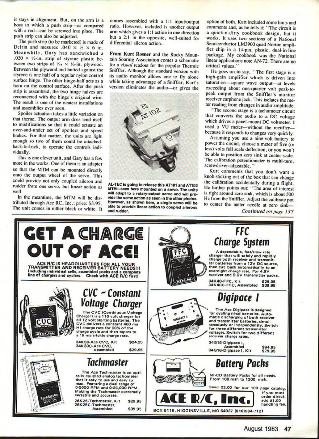
90-Degree Motion Transfer Module (MTM)
Back in the February column, a hot new item was featured called AL-I-SPAR, an all-aluminum spar with a very high strength-to-weight ratio designed by Gary Hutchison of Charlotte, MI. Gary has done it again — this time with a clever linkage package labeled the "90-Degree Motion Transfer Module" (MTM).
The unit consists of four Nylon parts that can be snapped apart and reassembled in seconds. As the name implies, it transfers motion at 90°. Unlike a conventional 90° bellcrank, which can introduce some non-linear action due to arm sweep, the MTM provides linear, very positive action. This makes it ideal for spoilers, flaps, and ailerons. The unit is light and installs neatly.
Recommended installation procedure:
- Glue a one-inch piece of plastic tubing to the front of the unit's case.
- Cut two more tubing pieces to act as spacers between ribs.
- Cut a length of wire that spans the rib bay plus one-half inch.
- Slide the wire through a rib, the tubing sections, and the opposite rib.
- Glue the spacers and the wire ends to the ribs for a neat, quick installation.
For pushrod action, the MTM parts are thick enough to drill and tap for an adjustable connection. Alternatively, drilling a hole through the face of the drive plate accommodates a simpler "90°-bend-in-a-wire" installation.
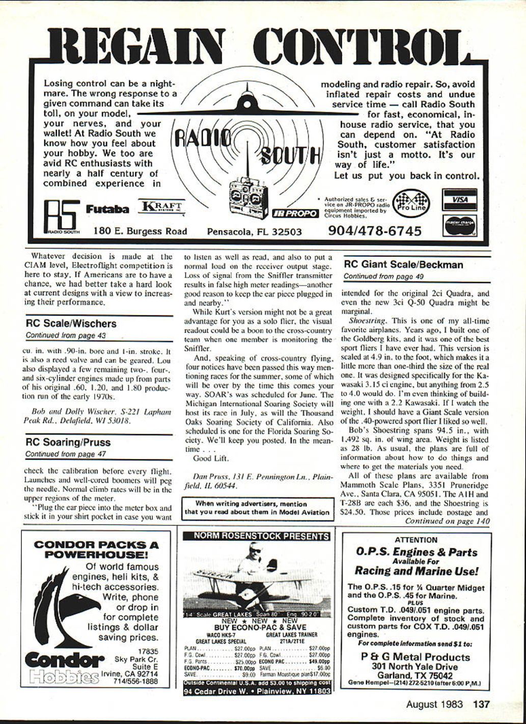
The output arm allows for fine adjustments. The arm has a T cross section so the MTM can be set up to actuate:
- Flaps (left position)
- Ailerons (center position)
- Spoilers (right position)
Mounting: units are retained by an inter-rib wire running through a tube glued to the front of the unit. Output to the control surface is via a push-strip (note: the slot in the strip allows neutral position adjustment). Input from the servo is via a pushrod:
- For flap and aileron units, use a threaded rod screwed into a tapped hole in the input flange.
- For the spoiler unit, use a regular clevis attached to a hole drilled through the input flange.
One mock-up wing has all three units mounted. The MTM stays in alignment, and on the arm is a boss to which a push strip (as compared with a rod) can be screwed in place and adjusted.
Push strip and horn assembly:
- The push strip to be marketed is made of Delrin and measures 0.040 x 1/2 x 6 in.
- Gary demonstrated a neat assembly using a 0.020 x 1/2-in. strip of styrene sandwiched between two strips of 1/4 x 1/2-in. plywood.
- Between the plywood and butted against the styrene is one half of a regular nylon control surface hinge; the other hinge half acts as the horn on the control surface.
- After the push strip is assembled, the two hinge halves are reconnected with the hinge's original wire, resulting in a very clean installation.
Spoiler actuation can be varied: the output arm can be modified to actuate an over-and-under set of spoilers and speed brakes. Units are light enough that two can be attached back-to-back to operate controls individually.
Gary is developing more accessories, including an adapter to mount the MTM directly onto a servo output wheel. This could provide coupled aileron and rudder control from one servo with linear action.
Distribution and options:
- Distributed through Ace RC, Inc.
- Price: $5.95
- Colors: black or white
- Supplied assembled with a 1:1 input/output ratio; an additional output arm is included that provides 1:1 action in one direction and 2:1 in the opposite, suitable for differential aileron action.
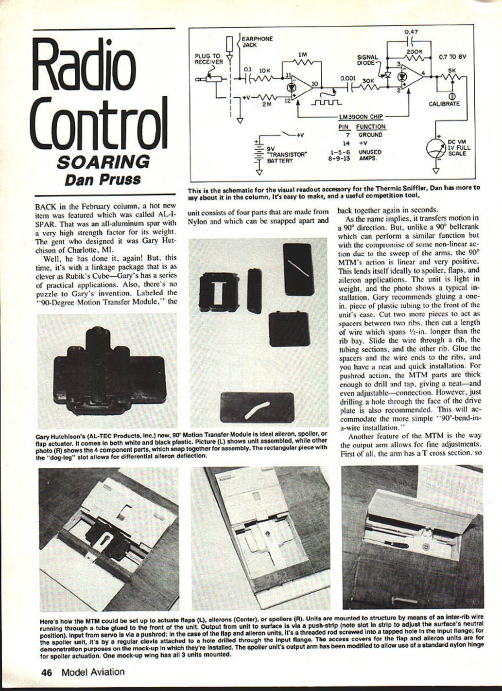
Thermic Sniffler — Visual Readout (Kurt Rosner / Rocky Mountain Soaring Association)
Kurt Rosner provided a schematic for a visual readout for the popular Thermic Sniffler. The standard Sniffler has an audio monitor that lets you fly solo while listening for lift; Kurt's version provides a visual option (or both audio and visual).
Circuit overview:
- The circuit uses two sections of a National Semiconductor LM3900 quad Norton amplifier (14-pin DIP).
- Kurt based his design on National applications note AN-72; he describes the circuit as a "quick-n-dirty cookbook design" with no critical component values.
- Stage 1: a high-gain amplifier driven into saturation (square-wave output) at levels exceeding about 0.25 V peak-to-peak from the Sniffler's monitor jack. This isolates the meter reading from changes in audio amplitude.
- Stage 2: a tachometer circuit that converts the audio to a DC voltage to drive a panel-mount DC voltmeter. Kurt used a VU meter (without its rectifier) because it responds quickly to changes.
Meter and power recommendations:
- Power with a 9-volt battery.
- Choose a meter with 5 volts full-scale deflection (or less) so you can position zero sink at the center of the scale.
- The calibration potentiometer should be multi-turn and screwdriver-adjustable.
- Avoid an exposed knob that could be accidentally moved during flight.
Calibration and use tips:
- The area of interest is around zero sink, approximately 500 Hz from the Sniffler.
- Adjust the calibrate pot to center the meter needle at zero sink and check the calibration before every flight.
- Launches and strong thermals can peg the needle; normal climb rates will be in the upper regions of the meter.
- Plug the earpiece into the meter box and keep it in your shirt pocket if you want to listen as well as read. Keeping the earpiece plugged in also provides a normal load on the receiver output stage.
- Loss of signal from the Sniffler transmitter can cause false high meter readings — another reason to keep the earpiece nearby.
Kurt notes that while the visual readout may not be a major advantage for solo fliers, it can be very useful for cross-country teams when one member monitors the Sniffler visually.
Upcoming Races
Notices have been received about several summer soaring races (some may already be past by the time you read this):
- SOAR — scheduled for June
- Michigan International Soaring Society — July
- Thousand Oaks Soaring Society (California) — July
- Florida Soaring Society — date scheduled
We'll keep you posted.
Good lift.
Dan Pruss 131 E. Pennington Ln. Plainfield, IL 60544
Transcribed from original scans by AI. Minor OCR errors may remain.

