
Radio Control: Soaring
Dan Pruss
The Star
As mentioned in the F3B report last month, the most-photographed model at the Fourth World Championships in York, England, was Ralf Decker's 2.8-meter beauty. Also mentioned was the fact that Ralf doesn't put a name on his birds, so we simply refer to his masterpieces as "Ralf's" or "Decker's Models."
Usually, a report like last month's is closely followed by a mailbag here containing inquiries for more details on a winner's model or on a model which differs from your favorite kit. This column will try to outjump the postman.
It should be noted that cameras didn't begin to click only after Decker was named Champion or when it seemed as though he would win. With his past record and bag of modeling surprises, Ralf commanded the attention of everyone with a camera bag the moment he first walked onto the field. After his 18.9-sec run in Speed in the first round, we just loaded the cameras a bit faster and more often.
Ralf, along with his design team, has been a step ahead of everyone else in model construction technology since he first showed up on the scene in South Africa in 1977 for the first F3B World Championships. His efforts in Belgium in 1979 weren't necessarily out-classed by the more popular Dassel; the latter just had a better European competition record and a more regimented team effort preceding it when it arrived for that World Championship.
A lot of folks say it was a toss-up in Sacramento as to who had the better display of technology, when comparing Decker's plane with the dozen Swiss birds called Spartakus.
In York, there were no questions.
Working in collaboration with Dieter Pfefferkorn and H. Schmid, "Ralf's Model" is an evolution of his Belgian model (which was later kitted in Germany and labeled Optima by the manufacturer). Although the kit is of fine quality, it doesn't match the original design with respect to Ralf's construction techniques and materials used.
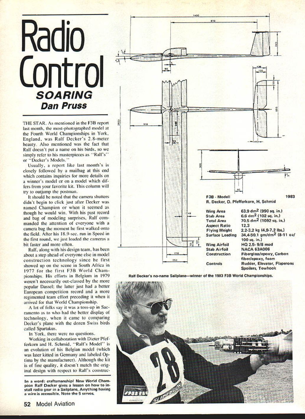
F3B - Modell 1983 (R. Decker, D. Pfefferkorn, H. Schmid)
- Wing area: 63.9 dm² (990 sq. in.)
- Stabilizer area: 6.6 dm² (102 sq. in.)
- Total area: 70.5 dm² (1,092 sq. in.)
- Aspect ratio: 12.3
- Flying weight: 2.2–3.2 kg (4.9–7.2 lbs.)
- Surface loading: 34.4–50.1 g/dm² (8–11 oz/100 sq. in.)
- Wing airfoil: HQ 2.5-9/8 mod
- Stabilizer airfoil: NACA 63A006
- Construction: fiberglass/epoxy, carbon fiber/epoxy, foam
- Controls: rudder, elevator, flaperons, spoilers, towhook
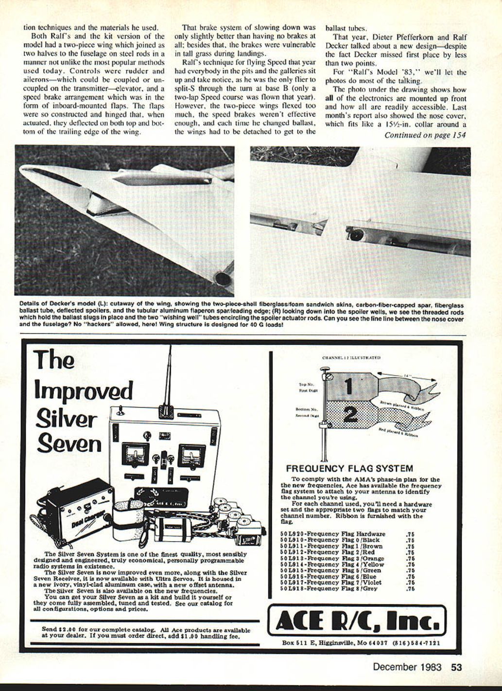
In a word: craftsmanship! New World Champion Ralf Decker gives a lesson on how to install radio gear in a sailplane. Anything having a wire is accessible. Note the five servos and the installation techniques and materials he used.
Controls and Flight Characteristics
Both Ralf's original and the kit version of the model had a two-piece wing which joined to the fuselage on steel rods—similar to the most popular methods used today. Controls consisted of rudder and ailerons (which could be coupled or uncoupled on the transmitter), elevator, and a speed-brake arrangement in the form of inboard-mounted flaps. The flaps were constructed and hinged so that, when actuated, they deflected both on the top and bottom of the trailing edge.
That brake system was only slightly better than having no brakes at all; further, the brakes were vulnerable in tall grass during landings.
Ralf's technique for flying Speed that year had everyone in the pits and galleries sit up and take notice: he was the only flier to split-S through the turn at base B (only a two-lap Speed course was flown that year). However, the two-piece wings flexed too much, the speed brakes weren't effective enough, and each time he changed ballast the wings had to be detached to access the ballast tubes.
That year, Dieter Pfefferkorn and Ralf Decker talked about a new design—despite the fact Decker missed first place by less than two points.
Electronics and Installation
The nose installation is notable: all electronics are mounted up front and readily accessible. The nose cover fits like a 15½-in. collar around a 16-in. neck. One screw secures the nose cover in place, and the whole unit and joints are waterproof.
Five servos are used:
- Two servos actuate the flaperons.
- One servo operates the rudder.
- One servo operates the horizontal stabilizer.
- One servo operates both the spoilers and the releasable towline.
The flaperons can be coupled with the rudder as desired. When used only as flaps and set for three tasks, the horizontal stabilizer is automatically trimmed to compensate for initial center-of-lift changes in the wing. Linkages are adjusted so that when tow release occurs the spoilers remain closed.
Instead of a tow ring, Ralf uses a steel ball attached to a cable. The ball is about 1/4 in. in diameter and is locked inside the fuselage with a plunger-type device during the tow. With the ball/socket device, the fuselage bottom is perfectly clean.
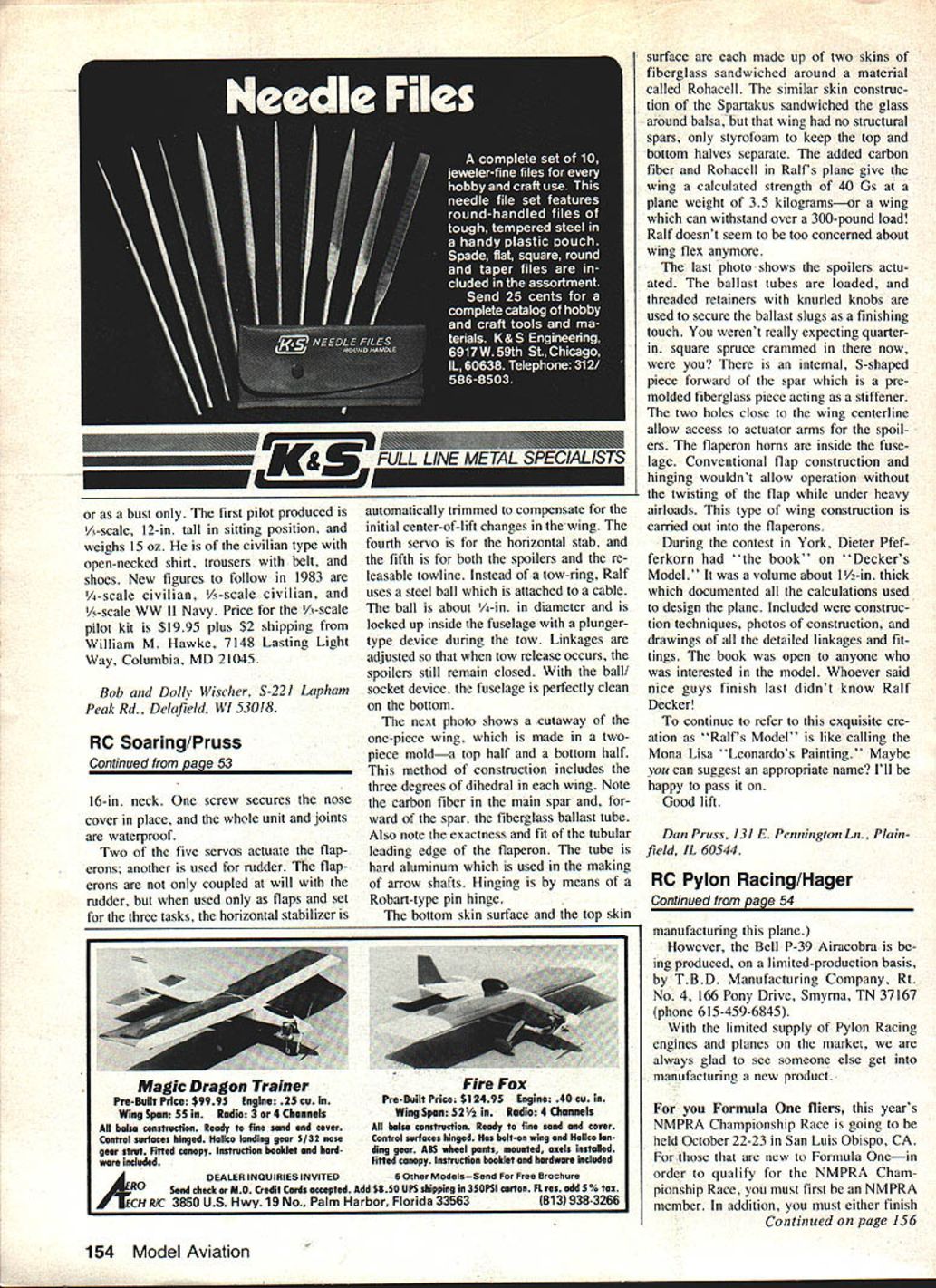
Wing Construction and Ballast
The one-piece wing is made in a two-piece mold—a top half and a bottom half. This construction includes three degrees of dihedral in each wing. The main spar contains carbon fiber, and forward of the spar is a fiberglass ballast tube. The tubular leading edge of the flaperon is hard aluminum (arrow-shaft material) with Robart-type pin hinging.
Both the bottom and top skin surfaces are each made of two layers of fiberglass sandwiched around Rohacell. The Spartakus wing used glass sandwiched around balsa and had no structural spars, only Styrofoam to separate the top and bottom halves. The added carbon fiber and Rohacell in Ralf's plane give the wing a calculated strength of 40 Gs at a plane weight of 3.5 kg—able to withstand over a 300-pound load. Ralf doesn't seem much concerned about wing flex anymore.
The spoilers are actuated from within; ballast tubes are loaded and secured with threaded retainers with knurled knobs. There is an internal S-shaped premolded fiberglass piece forward of the spar acting as a stiffener. Two holes close to the wing centerline allow access to actuator arms for the spoilers. The flaperon horns are inside the fuselage because conventional flap construction and hinging wouldn't allow operation without twisting the flap under heavy airloads. This internalized approach to flaperon construction avoids that problem.
Documentation and Sportsmanship
During the contest in York, Dieter Pfefferkorn had "the book" on "Decker's Model"—a volume about 1/2 inch thick documenting all calculations used to design the plane. It included construction techniques, construction photos, and drawings of detailed linkages and fittings. The book was open to anyone interested in the model. Whoever said nice guys finish last didn't know Ralf Decker!
To continue to refer to this exquisite creation as "Ralf's Model" is like calling the Mona Lisa "Leonardo's painting." Maybe you can suggest an appropriate name? I'll be happy to pass it on.
Good lift.
Dan Pruss 131 E. Pennington Ln. Plainfield, IL 60544
Transcribed from original scans by AI. Minor OCR errors may remain.

