
Radio Control: Soaring
By Dan Pruss
BACK when I was a kid, one could take his latest rubber‑powered pride and joy to the grocery store and have the butcher weigh it for him. That was when there seemed to be a market on every street corner and the butcher acted like one of the family. Walking into a supermarket today with a 12‑ft. sailplane might get you as far as the soup and pickles aisle. If you did manage to get as far as the counter with all of the precut, preweighed, prepackaged meats, your only contact with a butcher would probably be through an intercom and a plate‑glass wall. Forget about his scale.
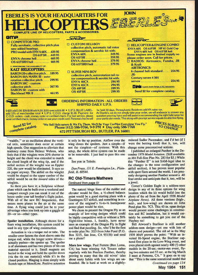
But that's OK, because David Munson (St. Louis, MO) has come up with a gadget that he calls the "Weight Stick." It's simply a length of aluminum bar, calibrated from the middle outward in pounds and ounces.
To use the Weight Stick, suspend whatever is to be weighed from the string at one end of the stick. By placing the stick on a table or a surface that has a sharp edge, move the stick until it teeters on the table's edge. A direct reading can then be made right from the printed scale. The scale ranges from a fraction of an ounce to 10 lb.
Being of solid aluminum and measuring 1/4 inch by 1 inch in cross section, the bar is straight and rigid and would also serve well as an alignment tool for spars and leading and trailing edges. The gadget is priced at $13.95 and should be in hobby shops by the time you read this. You can also order direct from: Weight/Stick Co., P.O. Box 29952, St. Louis, MO 63129. Add $2.00 for postage and handling.
Challenge of the Month — Specifications
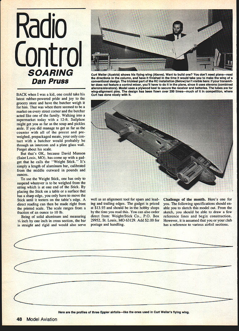
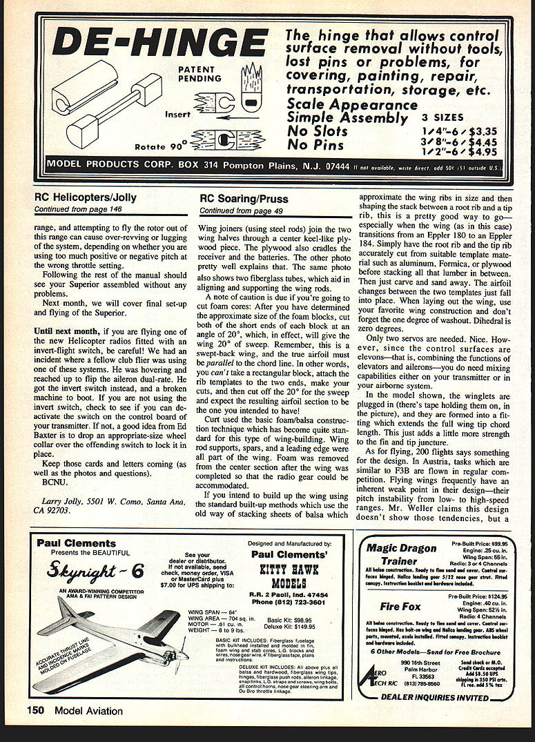
The following specifications should enable you to sketch this model and draw a few reference lines to begin construction. It is assumed you or your club has references for various airfoil sections.
- Wingspan: 2600 mm
- Leading edge sweep: 20°
- Centerline chord: 350 mm
- Centerline airfoil: Eppler 180
- Wing tip chord: 220 mm
- Wing tip airfoil: Eppler 184
- Incidence: 2° negative
- Elevons: 450 mm length
- Tip fins (winglets): 250 mm high; join two‑thirds in from wing tip; wing trailing edge forward — see photo
- Modest taper in winglets' side profile; designer claims it isn't critical. Winglets are basically flat plates.
- Center of gravity: 18% MAC. Suggested range: start at 15%, move back to 18%; do not exceed 20%
- Towhook position: 75% back along wing centerline
- Construction: Curt used foam cores
Construction
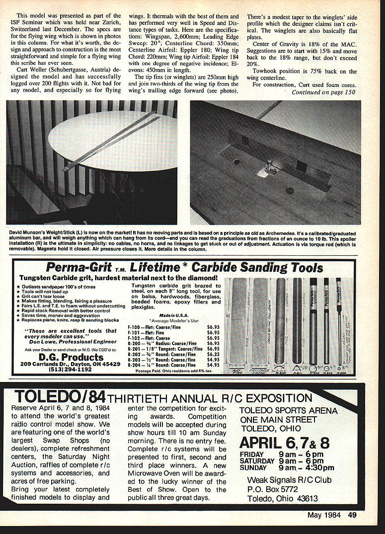
Wing joiners (steel rods) join the two wing halves through a center, keel‑like plywood piece. The plywood also cradles the receiver and the batteries. Two fiberglass tubes aid in aligning and supporting the wing rods.
A note of caution if you're going to cut foam cores: after determining the approximate size of the foam blocks, cut both short ends of each block at an angle of 20°, which will give the wing 20° of sweep. Remember, this is a swept‑back wing, and the true airfoil must be parallel to the chord line. In other words, you can't take a rectangular block, attach the rib templates to the two ends, make your cuts, and then cut off 20° for sweep and expect the resulting airfoil to be the one you intended.
Curt used the basic foam/balsa construction technique that has become standard for this type of wing building. Wing rod supports, spars, and a leading edge were all part of the wing. Foam was removed from the center section after the wing was completed so the radio gear could be accommodated.
If you intend to build up the wing using the standard built‑up methods—stacking sheets of balsa that approximate the wing ribs and shaping the stack between a root rib and a tip rib—this is a good approach, especially when the wing transitions from an Eppler 180 at the root to an Eppler 184 at the tip. Have the root rib and tip rib accurately cut from suitable template material such as aluminum, Formica, or plywood before stacking. Then carve and sand away; the airfoil changes between the two templates will fall into place. When laying out the wing, use your favorite wing construction method and don't forget the one degree of washout. Dihedral is zero degrees.
Controls and Servos
Only two servos are needed. However, since the control surfaces are elevons (combining elevator and aileron functions), you need mixing capabilities either on your transmitter or in your airborne system.
Winglets and Flight Characteristics
In the model shown, the winglets are plugged in (a taper holds them on in the picture), and they are formed into a fitting that extends the full wing tip chord length. This adds strength to the tip and helps prevent it from popping off.
Two hundred flights speaks well for this design. In Austria, tasks similar to F3B are flown in regular competition. Flying wings frequently have an inherent weak point in pitch stability across low to high speeds. Mr. Weller claims this design doesn't show those tendencies, but a "waddle," or an oscillation about the vertical axis, sometimes occurs at certain high speeds.
A suggestion from Helmut Wehren to alleviate that tendency: make the winglets 20% shorter in height, extend the chord to match the wing tip chord, and shape the winglet airfoil as an Eppler 220. On paper, that should eliminate the yaw. The airfoil on the winglet would be shaped so the upper camber of the airfoil is on the inward sides of the winglets.
So there you have it: a sailplane without plans that can be built over a weekend and is compact enough you can sneak it out of the house under your tall brother's flight jacket. With all the new RC frequencies, more planes can be in the air at the same time. A flying wing could be to your advantage when you hook up into a gaggle of 20 or so other types.
Spoiler Installation
Although shown for a foam wing installation, this spoiler system could be used in any wing construction.
- Actuation is via a torque rod or tube.
- The smaller screw fastens the short sleeve onto the torque rod, while the longer screw drives (actually pushes) the spoiler up.
- The spoiler is aluminum and has two pieces of thin can material epoxy‑bonded to it. Small magnets are buried in the wing and hold the spoiler down (via the tin‑can material) while it is closed.
- Hinging is done simply with Scotch tape or MonoKote. Positive actuation is only in the up position; airflow over the wing closes the spoilers.
- With this setup, the whole drive system can be made removable.
Just a simple—if not the simplest—of systems. I had to pass this one on.
See you in Toledo.
Dan Pruss 131 E. Pennington Ln. Plainfield, IL 60544
Transcribed from original scans by AI. Minor OCR errors may remain.

