
Radio Control: Soaring
Dan Pruss
Last month's column showed a unique way of mounting the airborne equipment in a fiberglass fuselage. However, that method adapted itself to fuselages that had a relatively flat bottom in their profiles compared with more teardrop-like designs.
Photos this month show a series of steps that can be applied to nearly all fuselage shapes, especially those with a more bulbous front end and an elliptical or circular cross section.
As stated last month, the main purpose of an installation of this type is to eliminate servo rails that are normally mounted transversely and epoxied to the fuselage sides. Under fuselage flexing resulting from a hard landing, these rails can start to work loose and leave you grounded. Wood side-rails help in mounting the lateral servo rails, but they can't always be installed neatly and effectively. The following method solves most of those problems.
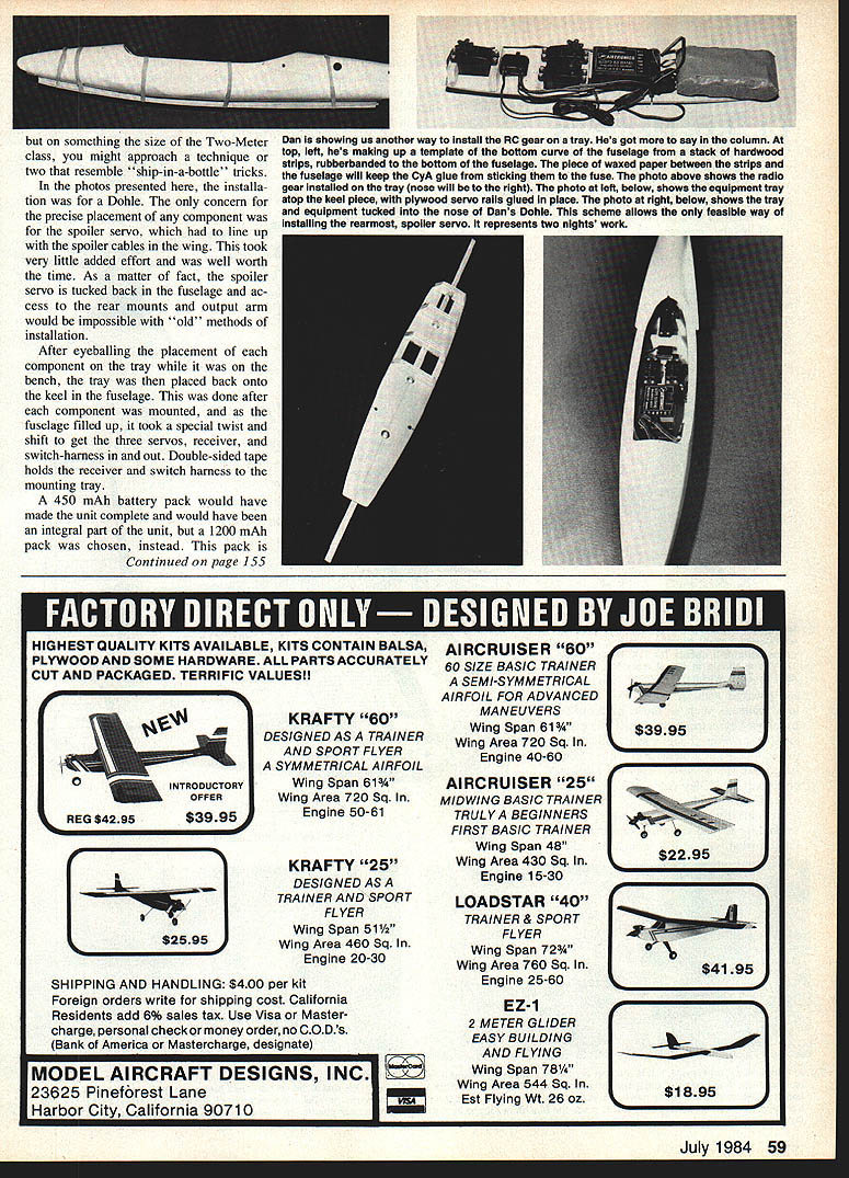
Keel-and-tray installation
Use of a wooden keel that serves as a mount for a plywood platform is the key to the installation system. The keel can be shaped to conform to any fuselage, and the platform or tray can be made to accommodate any radio installation.
- Determine the keel profile.
- A simple way is to take three 3/8 x 3/4-in. spruce strips and stack them.
- Hold the stack along the fuselage bottom with rubber bands. Use waxed paper between the fuselage and the wood strips.
- Use a cyanoacrylate (CyA) type of instant glue to laminate the three strips of spruce.
- Once set, the strips, now one curved piece, can be removed. Use the inside curve as a pattern to outline the bottom of the keel.
- Cut the keel.
- For the keel, use 1/4-in., five-ply birch plywood — something hard and dense.
- Estimate the keel height on the high side; this dimension isn't critical.
- After cutting the keel bottom to outline, check its fit to the inside of the fuselage. You may need to notch places where epoxy built up during fuselage construction.
- When satisfied with the fit, determine approximately where the airborne tray will sit in the fuselage, measure the keel height accordingly, and cut a straight line from the front of the keel to the back.
- Consider carrying the keel far enough back so it can later serve as a screw-in area for a tow hook.
- Tack-glue the keel in place.
- Tack-glue the keel in the fuselage (CyA was used here).
- Make the tray template and cut the tray.
- For the tray outline, fit a cardboard template that conforms to the inside of the fuselage but clears the sides by about an eighth of an inch. Some clearance is desirable.
- Transfer the template onto 1/8-in. plywood and cut out the tray.
- Mount the components on the tray.
- With the tray outside the fuselage, servo installation is straightforward: mount servo rails (1/4-in. plywood was used) wherever convenient.
- Since the goal is a removable airborne unit, ensure during the initial layout that nothing will obstruct the unit from slipping into the fuselage. On larger, scale-like ships this is usually not a problem, but on smaller models you must line things up so the unit will go in smoothly. On Two-Meter class ships you may need some "ship-in-a-bottle" tricks.
- Align and check controls.
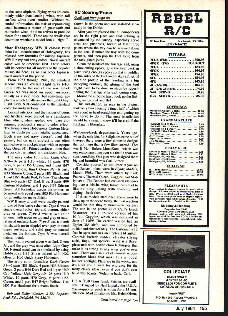
- In the installation shown (for a Dohle), the spoiler servo had to line up with spoiler cables in the wing. This required little extra effort and was worth it — the spoiler servo was tucked back in the fuselage where rear mounts and the output arm would have been inaccessible with older installation methods.
- After eyeballing component placement on the bench, place the tray back onto the keel in the fuselage after each component is mounted to check clearance. As the fuselage fills, it may take a special twist and shift to get the servos, receiver, and switch-harness in and out.
- Double-sided tape holds the receiver and switch harness to the mounting tray.
- Battery and final mounting.
- A 450 mAh battery pack would have made the unit fully integral, but a 1200 mAh pack was used and installed separately in the Dohle shown.
- When all components are in place and nothing is obstructed by the canopy (especially servo arms and pushrods), locate at least three points where the tray can be screwed down to the keel.
- Remove the tray with the components, then pop the keel loose from the tack-glued joints.
- Permanently glue the keel.
- Clean the inside of the fuselage and, using a slow-curing epoxy, glue the keel back in place. Use enough epoxy so it puddles up the sides of the keel and makes a fillet.
- If the fuselage side profile has a large contour, do the gluing in steps, repositioning the fuselage after each curing step.
- Mount the airborne tray, hook up the linkages, and fly.
This installation, as shown in the photos, took only two evenings — half of that time was spent thinking through the process and getting up the nerve to do it. The next installation should be a snap. This method will be useful whenever the fuselage is fiberglass.
Welcome-back Department
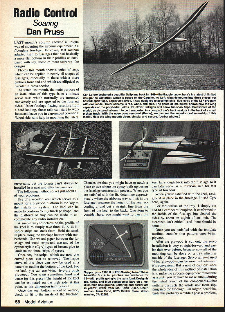
Years ago, when the only kits for sailplanes came out of Europe, a few domestic designs got many fliers started. That was B.M.—Before MonoKote—which was one reason anything over six feet in span was considered big. One gentleman who designed them big and beautiful was Carl Lorber.
Consider yourself an old-timer if you recall Dancer — plans were in Flying Models, March 1968. Carl designed others: Prancer, Thermal Curler, Gaggler, and Mollymawk. The Dancer had one-inch rib spacing over a 144-inch wing. You had to like building — along with covering and doping — back then.
If those models showed up on the scene today, the first reaction would be that they're brand-new designs. The one in the photos is Carl's latest: Easterner. It's a 12-foot version of the 10-foot Gaggler, which was designed in June of 1969. The earlier version had an Eppler 385 airfoil and was controlled by rudder and elevator only. The Easterner is 12 feet in span and has an Eppler 214 airfoil. Controls include rudder, elevator (flying stab), flaps, and spoilers. The wing is a three-piece unit with construction techniques that make it as strong as any wing you've seen. There are also many innovative construction ideas that make this a model-builder's delight. Plans are in the works and will be a set you'll want for reference for many clever ideas, even if you never build this beauty. Welcome back, Carl.
Transcribed from original scans by AI. Minor OCR errors may remain.

