
Radio Control: Sport Aerobatics
Ron Van Putte
Preventive maintenance note
We all have our pet peeves. One of mine is the misspelling of the word "preventive." It has been misspelled so often that some dictionaries even acknowledge "preventative" as an acceptable variation. My December 1979 column discussed periodic system maintenance to preclude failures and someone at Model Aviation really stuck it between my ribs when the column contained "preventative maintenance." Sorry. I really do know better. (Editor's Note: Guess we all do, now.)
Installing retracts in foam wings
- Identify the bottom of the wing
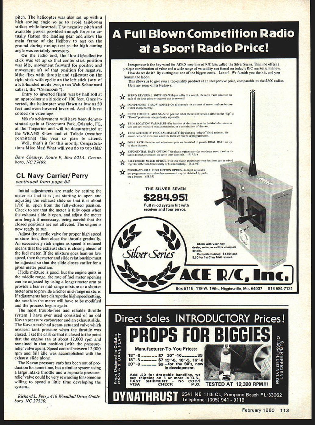
- The first thing I do when installing retracts in foam wings is to identify the bottom of the wing. This is important because the gear mechanism is mounted flush with the bottom of the wing, as shown schematically in Fig. 1. (Fig. 1 is exaggerated for clarity.) Consequently, all cuts in the foam should be made perpendicular to the bottom of the wing.
- Cutting the foam
- There are many ways to cut the foam for gear installation, but I prefer to use a 1/4-in. X-Acto saw blade with the back removed for straight cuts and a coping saw blade for circular cuts. Others may prefer cutting with hot nichrome wires and sharpened bottoms of drink cans, but I don't like them as well as what I use.
- Layout and marking
- Lay out the retract installation on the bottom of the wing using a sharp felt-tipped pen. After referring to the aircraft plans, mark the location of the gear pivot axis and the wheel well on the wing as shown in Fig. 2.
- The wheel well should be approximately 1/2 inch larger in diameter than the main gear wheels which will be used. Be sure that the locations of the pivot axis and wheel well are accurate since the gear installation is "set in concrete" from here on.
- Channel and facing
- Next, mark the location of the channel into which the gear mechanism will recess. The channel should be barely wider than the gear mechanism.
- Draw lines parallel to the channel and spaced 3/8 inch to each side, as shown in Fig. 3. Later this 3/8-in. space will be filled with 1/8-in. balsa facing.
- The channel should be long enough to permit the retract mechanism to be installed at the location of the pivot axis, plus enough for a 1/16-in. balsa facing at the end of the channel.
- Mounting plate
- Most aircraft plans suggest that the retract mechanism be bolted to a plywood plate 3/16 to 1/4 in. thick. I use a 1/4-in. plate as shown in Fig. 4.
Helicopter setup and aerobatics
The helicopter was also set up with a high coning angle to avoid tail-boom strikes while inverted. The negative pitch and available power provided enough force to actually flatten the landing gear and allow the main frame of the Heliboy to rest on the ground during run-up tests, so the high coning angle was certainly necessary.
On the radio end, the throttle/collective stick was set so that center stick position was idle, movement forward produced positive pitch, and movement aft of center produced negative pitch. Mike flies with throttle and tail-rotor on the right stick and cyclic on the left stick (a sort of left-handed Mode 2, or as Walt Schoonard calls it, the "Commode").
Entry to inverted flight was by a half roll at an approximate altitude of 100 feet. Once inverted, the helicopter was flown as low as 50 feet and even hovered inverted. And all of this is recorded on videotape.
Mike's achievement will be demonstrated again at Rosemont Park, Orlando, FL, at the Tangerine, and will be demonstrated at the WRAMS Show and at Toledo (weather permitting) this year — so plan to attend.
Well, that's it for this month. Congratulations, Mike Mas! What will you do to top this?
Dave Chesney Route 9, Box 621A, Greensboro, NC 27409.
Transcribed from original scans by AI. Minor OCR errors may remain.

