
Radio Control: SPORT AEROBATICS
Ron Van Putte
ONE of the great things about our hobby is that you get to meet a lot of nice people. In what other hobby are people so willing to give their time to help beginners? Aside from the occasional oddball, the radio control fraternity seems to draw mostly people who are pleasant to be around.
I was gratified, but not really surprised, to hear about what F. Duayne Sims' flying buddies did for him. Duayne moved to Indio, California, in January 1976. There he met a group of RC fliers who welcomed and assisted him in constructing and learning to fly his first RC airplane.
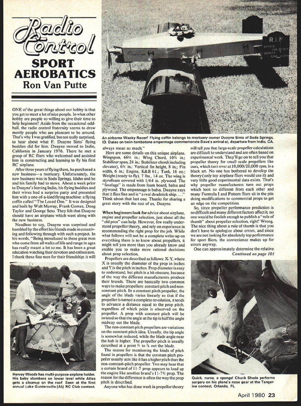
After three years of flying there, he purchased a new business—a mortuary. Unfortunately, the new business was in Soda Springs, Idaho, and he and his family had to move. About a week prior to Duayne's leaving Indio, his flying buddies and their wives had a surprise party and presented him with a one-of-a-kind flying machine: a flying coffin called "The Loved One." It was designed and built by Walt Murray, Frank Gomez, Doug Taylor and George Seto. They felt that Duayne should have an airplane which went along with the new business.
Needless to say, Duayne was surprised and humbled by the effort his friends made in conceiving and following through with such a project. In his words, "Being introduced to these great men who come from all walks of life and range in ages has really meant a lot to me. It has been a great education watching their devotion and enthusiasm. I thank these fine men for their friendship; it will always mean so much."
Here are some details on this unique airplane:
- Wingspan: 66½ in.
- Wing chord: 10¾ in.
- Stabilizer span: 24 in.
- Stabilizer chord (including elevator): 6½ in.
- Vertical fin height: 8 in.
- Fin width: 6 in.
- Engine: K&B .61
- Tank: 16 oz.
- Weight (ready to fly): 7 lb 14 oz
The wing is Styrofoam covered with 1/64 in. plywood. The "fuselage" is made from foam board, balsa and plywood. The empennage is balsa. Duayne says that it flies fine and is "a real deadstick ship."
Think about that last one. Thanks for sharing a great story with the rest of us, Duayne.
Propeller Selection and Pitch Types
When beginners look for advice about airplane, engine and propeller selection, just about all the "old pros" can help. However, few really understand propeller theory, and rely on experience in recommending the right prop for the job. While what follows will not be a complete write-up on everything there is to know about propellers, it might tell you more than you already know and enable you to make more rational decisions about prop selection.
Propellers are described as X–Y, where X is usually the diameter of the prop in inches and Y is the pitch in inches. Prop diameter is easy to understand, but pitch is a bit obscure because different manufacturers produce their brands differently.
There are basically two common ways to make propellers:
- Constant-pitch: the blade angle varies linearly so that if the propeller is turned a complete revolution, it tends to advance a distance equal to the prop pitch, regardless of which point is observed on the propeller. A constant-pitch prop will be twisted so that the angle at the tip is half the angle midway out the blade.
- Non-constant-pitch: variations on the constant-pitch idea. Usually, the tip angle is somewhat reduced while the blade angle near the hub is higher. The propeller pitch is usually described at a point 3/4 to 7/8 out on the blade.
The constant-pitch propeller usually acts like it has a higher pitch than the non-constant-pitch propeller. You may hear that one brand's 11–7 prop appears to load up the engine like another brand's 11–7½ prop. The reason can often be the way the prop pitch is described.
Anyone who has done work in propeller theory will tell you that large-scale propeller calculations are difficult and often based on experimental work. Propeller theory for small-scale props, which turn over 10,000–20,000 rpm, is a black art. Very little good experimental data exists for model props, which is why manufacturers produce props that look very different and many competitive fliers modify commercial props to gain an edge.
Load Factor Rule and Example
Despite the uncertainty, a useful rule of thumb exists for comparing approximate relative thrust. One can approximately determine the relative thrust that two propellers will deliver by comparing their load factors.
Load factor = pitch × (diameter)^3
Example:
- An 11–8 prop has a load factor of 8 × 11^3 = 8 × 1331 = 10,648.
- An 11½–7 prop has a load factor of 7 × 11.5^3 ≈ 7 × 1520.875 ≈ 10,646.
According to the rule, the thrust developed by an 11–8 prop should be about the same as for an 11½–7 prop.
We all know that a small engine will not turn a large prop. The trick is to determine a typical load factor range for different engines and vary prop characteristics to get the desired performance.
Engine Displacement and Load Factor Ranges
The following table (from an article by E. J. "Rich" Richburg) gives typical load factor ranges for engines of various displacements. Find the displacement of your engine and read across for the load factor range.
- .05 — 400–680
- .09 — 900–1500
- .15 — 1500–2500
- .19 — 2500–3000
- .20 — 2600–3650
- .25 — 3600–4600
- .29 — 4300–5500
- .30 — 4500–6200
- .36 — 5000–7000
- .45 — 6500–8400
- .60 — 7600–10800
- .80 — 9900–14000
It is intentional that some ranges overlap since a hot .35 can swing more prop than a marginal .40. After selecting a load factor, calculate the load factors of several prop diameter/pitch combinations to find the closest match.
After the initial selection, try props with slightly higher and lower load factors to see which satisfies the airplane/engine/pilot combination. If more speed is desired, try a prop with a higher load factor. For better low-speed thrust, generally use a prop with a lower load factor.
The load factor chart won't tell you whether you would have better luck with one manufacturer's prop or another's, but it gives a rational starting point. Give the chart a try the next time a beginner asks what prop to put on his first airplane. You might even use it to improve vertical performance on your latest airplane.
Bending Balsa with Ammonia
For a long time I used water to soak balsa sheet prior to bending it sharply, like on wing leading edges. Water gave marginally successful results. Then someone suggested using ammonia to soak the balsa. Anyone who has used ammonia knows that it gives fantastic results, but I never knew why.
The Lehigh Valley R/C Newsletter, edited by Tom Bilheimer, had a short article on bending balsa wood which explained it:
"To bend balsa wood, soak it in ammonia water (aqua ammonia is best) for 15 to 45 minutes (but not longer than 45 minutes). What happens is that the balsa wood structure—the orderly arrangement of the microscopically elongated hollow cellulose tubes, which are held together by a natural adhesive called lignin—are temporarily distorted when the ammonia solution is applied and the balsa wood is bent into a new shape. When the solution of water and ammonia evaporates the lignin returns to its original strength. So now we all know why ammonia works."
Closing
About the time the next column comes out, many of you will be getting ready to fly again after a winter's hibernation. The next column will feature suggestions on how to get the airplane/engine/radio/pilot combination started on the right foot.
Ron Van Putte 12 Connie Drive Shalimar, FL 32579
Transcribed from original scans by AI. Minor OCR errors may remain.

