
Radio Control: SPORT AEROBATICS
Ron Van Putte
As I sat down to write this column, I realized that it was five years ago that my first column was sent in to Model Aviation. During that first column I introduced myself and described my plans for the future. It occurred to me that many current readers never read that first column, and that it is appropriate to update the situation on this anniversary.
I am an aeronautical engineer with one degree from Purdue University and two degrees from the University of Michigan. From 1959 to 1979 I was an officer in the Air Force. After retirement and a six-month mandatory waiting period (federal regulation), I returned to the job I had left at the Air Force Armament Laboratory, but as a Civil Service employee this time. My work involves analyzing the effects of new weapons on the aircraft which carry them, and vice versa.
My involvement in our fascinating hobby began when I was a college freshman in 1954, and has continued since then with several delays for college. During the last 26 years I have flown a wide spectrum of radio/aircraft/engine combinations. One of these days I'll publish a picture of my first radio system, which featured a home-built ground-based transmitter (it had an eleven-foot antenna), an ECE vacuum-tube receiver, a Bonner SN escapement, two 22½‑volt and four 1½‑volt batteries. Despite the relative crudity, high weight and unreliability of that radio system, I had many great flights with one of Harold deBolt's Kitten airplanes. We never had any idea that advances in electronics would produce the kind of radios we have today.
A long time ago I sat down and listed all the airplanes I've owned and was surprised to discover that my average was about one airplane for every year in the hobby. Included in that list are:
- deBolt Sonic Cruiser and Viscount
- Two Goldberg Senior Falcons
- Midwest Esquire
- Lanier P-51
- Bridi Kaos 60
- Du-Bro Cherokee Arrow
- Beachcomber
- Intruder
- Andrews Trainermaster
- Phoenix III
- Phoenix V
- Two Phoenix VIs
- Phoenix VIII
Once involved in RC pattern competition, I was hooked. My first pattern contest was in Indianapolis, Indiana, in 1966 where my Senior Falcon was demolished by a maneuver called a Scrambled Eight (an overhead eight with half up, half inverted). You'd think that that would have been the end of my pattern flying career, but I was encouraged by a good friend named Don Lowe. Over the years Don has developed into a world-class pattern flier and he serves as a model for the kind of flier I want to be. I hope people can see some of the "smooth" Lowe style in the way my Phoenix flies.
Last fall I moved up after four years in Advanced and now fly the Expert pattern with a fair-to-good degree of competence at contests throughout the Southeastern states. Once I get the Figure M with Half Rolls and the Eight Point Roll sorted out, my scores will improve. My competitive drive has continued undiminished over the years and the sweaty palms, shaking knees and pounding heart routine repeats itself each time I step to the flight line at a contest. I will continue to compete in pattern contests if the drive is still there, so look for me on the contest trail for a long time to come.
Periodically I receive letters with questions that I've answered in an earlier column. Some of these have been answered privately, but when there is sufficient general interest to warrant a reprint or a fresh answer, I like to include it in the column. Such is the case with a letter from Paul Niner, who is a member of the Prince Georges Flying Club in La Plata, Maryland, and a pre-med student at Notre Dame. Paul wrote:
"In the past two years I've had a growing interest in the canard concept of aerodynamics (tail ahead of the wing, R/C) and am in the preliminary design process of an RC canard pattern airplane. I recall the PGRC Club meeting several years ago at which you presented a film of a canard airplane that you and your students at Annapolis had successfully designed, built and flown. Would it be possible to obtain the plans for your canard airplane and any technical information on the canard concept?"
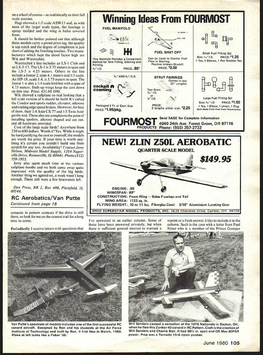
Boy, does that bring back memories! My students in a stability and control course at the Air Force Institute of Technology (not Annapolis, sorry Paul) in 1966 were tasked with applying the theory that they had learned to the canard concept. Together my students and I designed, and I built, a 6-foot span model of it, which flew in March 1966. It was displayed at the Toledo R/C Conference and the interest it generated resulted in an article called "Canard Pointers" being published in the April 1968 American Aircraft Modeler magazine. The model was eventually destroyed due to a battery pack failure during an Air Force test flight piloted by Don Lowe. I called the airplane the Ascender, and if you saw it in flight, you know what I mean. You probably have also seen an Atlantic R/C canard that was built earlier and flown by Don Lowe. It was featured in a Model Aviation article published in the March 1977 issue. They produced a kit which may still be available. Where are you Charlie and Bill—let me hear from you?
Canard design basics
Now, back to technical information on canard aircraft. Many people think the canard design is tricky and that the airplanes are inherently unstable. That is definitely not true. One of the most stable airplanes I ever flew was my canard design. It is true that improper center of mass location and/or insufficient consideration of directional stability will cause a nasty airplane, but that's not the fault of the canard concept.
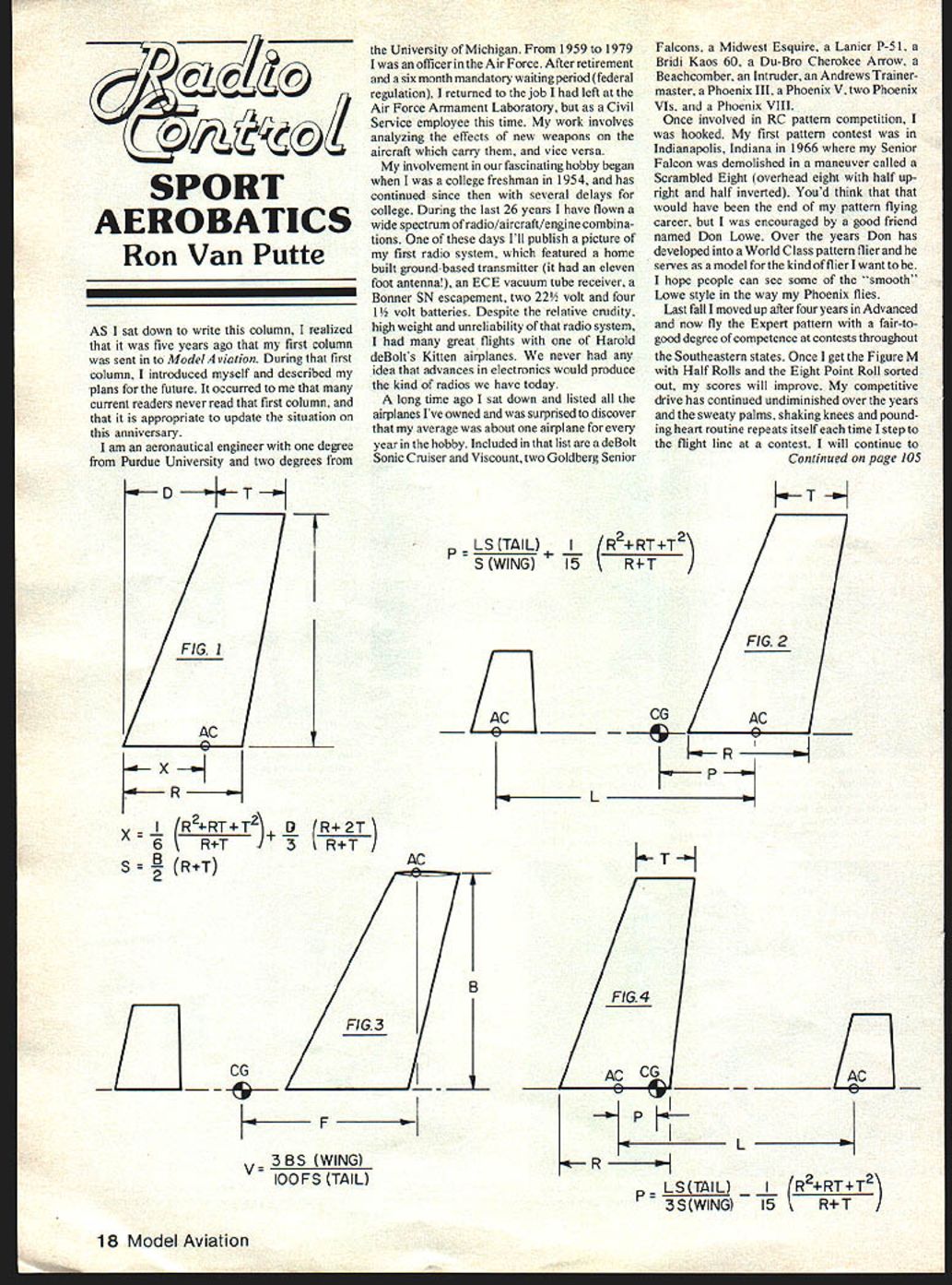
In finding the proper center of mass, the first consideration is the location of the aerodynamic center of the wing. There are all sorts of "cookbook" techniques to do this, but the best I've found is the X equation of Figure 1. Also calculate S, the wing panel area, for later use. Next, the aerodynamic center of the horizontal stabilizer is determined in the same way, using Figure 1 again, with numbers corresponding to the stabilizer. Again, calculate S, this time being the stabilizer panel area.
You will note that no mention has been made so far that this is a canard design being considered. In fact, at the end of this discussion you will have two techniques for center of mass calculation corresponding to either a conventional or a canard aircraft. The only difference between the two equations will be a minus sign on one term and a factor of three in another term.
Determine the distance between the aerodynamic centers of the wing and horizontal stabilizer and locate the proper center of mass as shown in Figure 2 by using the P equation. This center of mass location guarantees that the aircraft will be statically stable in pitch. After test flights have been made, it may be desirable to move the center of mass toward the rear of the airplane in order to improve the pitch response of the aircraft.
The second part of successful canard aircraft design is to provide adequate directional stability. On canard aircraft, it is often desirable to put vertical fins on the tips of relatively long, swept wings rather than installing a large vertical fin on the fuselage. Again using Figure 1, the aerodynamic center location of the vertical fins is calculated. Also determine S_v, now being the vertical fin area. The V equation in Figure 3 will tell you if the vertical fins are the right size.
- If V is about equal to one, you're in good shape.
- If V is somewhat greater than one, the vertical fins are too small.
- If V is less than one, the vertical fins are too big.
If you have to adjust the vertical fin area, redo the aerodynamic center calculation and re-determine V until it comes out about one. By the way, the V equation assumes you have two vertical fins. If you only have one, shoot for a value of two for V.
That's really all there is to preliminary canard aircraft design, but both steps are major hurdles on the way to success. Of course, there's no guarantee that the center of mass that your design will end up where the calculations say it's supposed to be. However, there's nothing new about that situation for conventional airplanes, either.
Conventional aircraft center of mass
For those of you who weren't really interested in canard design, but who are interested in determination of the proper center of mass location for a conventional aircraft, I have a treat for you. If you make the calculations for the wing and horizontal stabilizer using Figure 1, you can go directly to the calculation of the proper center of mass of a conventional aircraft by using Figure 4.
Next month's feature will be all about how to prepare for your first contest.
Ron Van Putte 12 Connie Drive Shalimar, FL 32579
Transcribed from original scans by AI. Minor OCR errors may remain.

