
Radio Control: SPORT AEROBATICS
Ron Van Putte
Zonker kits and contacts
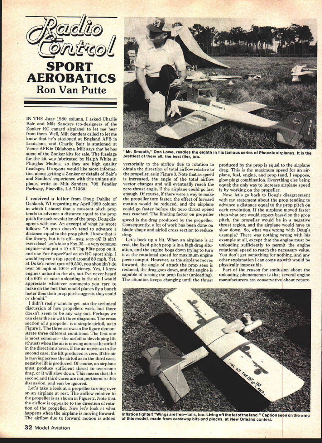
In the June 1980 column I asked Charlie Bair and Milt Sanders (co-designers of the Zonker RC canard airplane) to let me hear from them. Milt Sanders called to let me know he’s stationed at England AFB in Louisiana, and Charlie Bair is stationed at Vance AFB in Oklahoma. Milt says he has some Zonker kits for sale. The fuselage for the kit was fabricated by Ralph White at Fliteglas Models, so they are high-quality fuselages.
If anyone would like more information about getting a Zonker or details of Bair’s and Sanders’ experience with this unique airplane, write to: Milt Sanders 708 Fendler Parkway Pineville, LA 71360
Propeller pitch, advance, and a letter from Doug Dahlke
I received a letter from Doug Dahlke of Oshkosh, WI regarding my April 1980 column in which I stated that a constant-pitch prop tends to advance a distance equal to the prop pitch for each revolution of the prop. Doug disagreed. An excerpt of what he wrote follows:
"A prop doesn't tend to advance a distance equal to the prop pitch. I know that is the theory, but it is off—way, way off. It ain't even close. Let's take a Fox .35 — a very common engine — and put a 10 x 6 Top Flite prop on it, and use Fox SuperFuel on an RC sport ship. I would expect a top speed around 80 mph. Yet, at Duke's rated rpm of 9,500, you shouldn't do over 56 mph at 100% efficiency. Yes, I know engines unload in the air, but I've never heard of a 60% or more unloading in the air. I would appreciate whatever comments you care to make on the fact that model planes fly a bunch faster than their prop pitch suggests they could or should."
I didn't really want to get into the technical discussion of how propellers work, but there doesn't seem to be any way out. Perhaps we can clear the air with three diagrams (described below).
How a propeller airfoil works (description of figures)
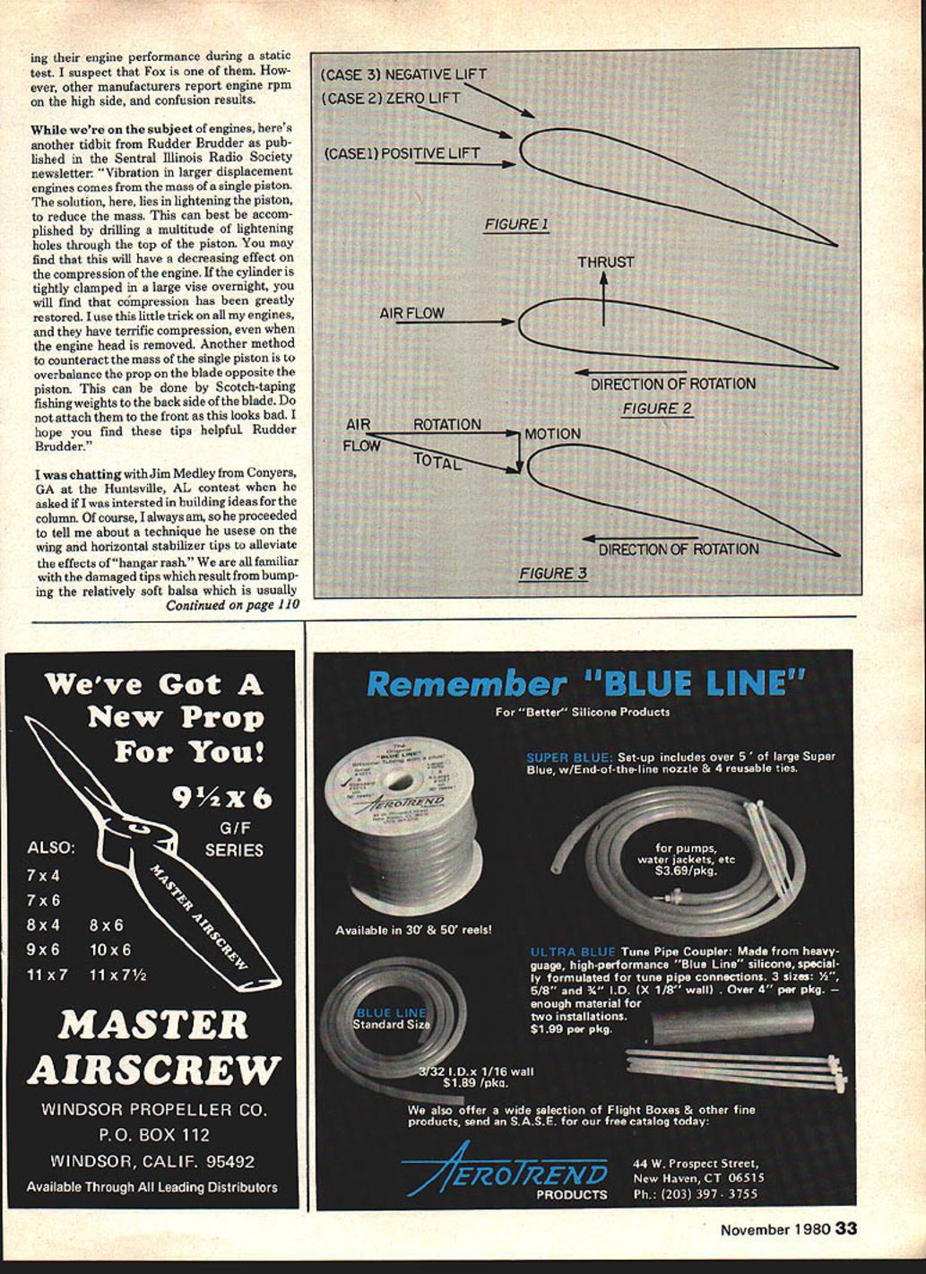
The cross section of a propeller blade is a simple airfoil. Consider three conditions for airflow across that airfoil (Figure 1):
- First (most common): the airfoil is developing lift (thrust) when the air is moving across the airfoil in the thrust-producing direction.
- Second: the airflow produces zero lift.
- Third: the airflow produces negative lift.
Only the first case is pertinent to producing thrust; the second and third correspond to no thrust or reverse/negative thrust and can be ignored for this discussion of normal forward flight.
Now consider a propeller turning with the airplane at rest (Figure 2). The airflow relative to the propeller is opposite the direction of rotation. When the airplane moves forward, the airflow from forward motion is added vectorially to the airflow from rotation to give the total airflow direction relative to the propeller (Figure 3). As airplane speed increases, the angle of that total airflow vector changes and eventually will reach the zero-thrust angle if the airplane could go fast enough.
If there were a way to make the prop turn faster, the effect of forward motion would be reduced and the airplane could go faster before zero thrust is reached. The limiting factor on propeller rotational speed is the drag produced by the propeller, so a lot of work has been done on blade shape and airfoil cross section to reduce drag.
Engine unloading and why Doug’s example isn’t paradoxical
When an airplane is at rest, a fixed-pitch prop presents a high load and the engine bogs down to some rotational speed determined by engine torque and prop drag. As the airplane moves forward, the angle of attack the prop sees is reduced, drag decreases, and the engine can turn the prop faster — this is called unloading. The situation changes until prop thrust equals airplane drag; that equilibrium determines maximum speed for the airplane, engine, propeller, fuel, and glow plug combination.
Regarding Doug’s example: nothing physically impossible is occurring. If the airplane were to move faster than the speed suggested by the prop pitch, the prop would be in a negative thrust region and the airplane would slow. What happens in practice is that the engine unloads enough in flight to allow higher RPM than the static (on-ground) numbers, so the plane can achieve higher speeds than a naive pitch-only calculation would predict. You don’t get something for nothing: the engine must be unloading sufficiently to permit the necessary RPM. Part of the confusion is that several engine manufacturers are conservative (or inconsistent) in reporting engine performance from static tests.
Engine vibration tip (from Rudder Brudder)
From the Central Illinois Radio Society newsletter, “Rudder Brudder” offers a tip for vibration in larger-displacement engines:
"Vibration in larger displacement engines comes from the mass of a single piston. The solution lies in lightening the piston to reduce the mass. This can best be accomplished by drilling a multitude of lightening holes through the top of the piston. You may find this will have a decreasing effect on compression of the engine. If the cylinder is tightly clamped in a large vise overnight, you will find that compression has been greatly restored. I use this little trick on all my engines, and they have terrific compression, even when the engine head is removed. Another method to counteract the mass of the single piston is to overbalance the prop on the blade opposite the piston. This can be done by Scotch-taping fishing weights to the back side of the blade. Do not attach them to the front as this looks bad. I hope you find these tips helpful. Rudder Brudder."
Wing and horizontal stabilizer tip protection
I was chatting with Jim Medley from Conyers, GA at the Huntsville contest when he described a simple technique he uses on wing and horizontal stabilizer tips to reduce "hangar rash." We’re all familiar with damage from bumping the relatively soft balsa used in tips. Jim’s technique is easy to implement and greatly improves ding resistance.
Method A (for foam wings):
- After the foam wing is sheeted and with a flat piece of 1/16-in. balsa glued on the tip, mark a straight line along the center of the tip airfoil and draw a line on the end grain from the tip to the trailing edge.
- Cut the tip off to this line and sand the cut surface smooth and true.
- Cut a block of very hard balsa to shape and glue it on the end.
- When dry, sand to final contour and seal with a thin coat of 50/50 thinned dope.
- Final covering should be iron-on film or tissue and dope.
Method B (for built-up wings with a hard sheet):
- Glue on a simple hardwood tipplate shaped to the contour.
Method C (a plywood-sandwich tip for soft balsa tips):
- On the balsa tip piece, mark the centerline and then two parallel lines 1/32-in. to either side of the centerline.
- Cut a piece of 1/16-in. plywood in the planform shape of the tip to be installed.
- Using a cyanoacrylate glue (Hot Stuff, Zap, or Jet), glue the plywood piece to the balsa plate, perpendicular to the tip and aligned with the parallel lines.
- Cut two soft balsa blocks roughly to shape and glue them to the plate and the plywood.
- Sand the tip to shape. The plywood serves as a sanding template and is barely visible when finished, but it significantly reduces damage from dings.
Another method is to glass the tip using a small patch and warm dope to harden. All these techniques stiffen and protect tips.
Closing
As this was written I was in the final stages of completing my new Phoenix 8 for the Nats. I had nine days to finish the airplane, test fly it, make necessary trim adjustments, and get in some practice before leaving for Wilmington, OH. One of these years I will finish an airplane in sufficient time so I won’t have any excuses for my competition performance.
Ron Van Putte 12 Connie Drive Shalimar, FL 32579
Transcribed from original scans by AI. Minor OCR errors may remain.

