
Radio Control: Sport and Aerobatics
Ron Van Putte III 111 Sleepy Oaks Rd. Ft. Walton Beach, FL 32548
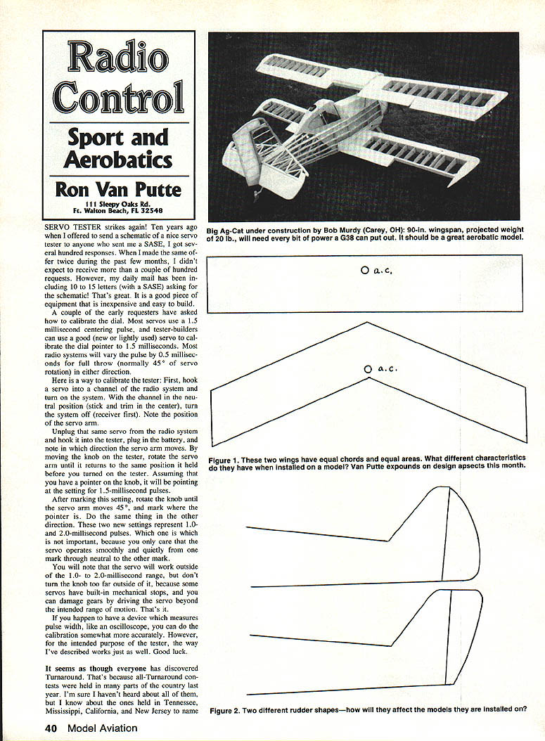
SERVO TESTER strikes again
Ten years ago when I offered to send a schematic of a nice servo tester to anyone who sent me a SASE, I got several hundred responses. When I made the same offer twice during the past few months, I didn't expect to receive more than a couple of hundred requests. However, my daily mail has included 10 to 15 letters (with a SASE) asking for the schematic! That's great. It is a good piece of equipment that is inexpensive and easy to build.
A couple of the early requesters have asked how to calibrate the dial. Most servos use a 1.5-millisecond centering pulse, and tester-builders can use a good (new or lightly used) servo to calibrate the dial pointer to 1.5 milliseconds. Most radio systems will vary the pulse by 0.5 milliseconds for full throw (normally 45° of servo rotation) in either direction.
Calibrating the tester
- Hook a servo into a channel of the radio system and turn on the system. With the channel in the neutral position (stick and trim centered), turn the system off (receiver first). Note the position of the servo arm.
- Unplug that same servo from the radio system and hook it into the tester, plug in the battery, and note in which direction the servo arm moves.
- By moving the knob on the tester, rotate the servo arm until it returns to the same position it held before you turned on the tester. Assuming you have a pointer on the knob, it will be pointing at the setting for 1.5-millisecond pulses. Mark this setting.
- Rotate the knob until the servo arm moves about 45°, and mark where the pointer is. Do the same thing in the other direction. These two new settings represent approximately 1.0- and 2.0-millisecond pulses.
- Which mark is 1.0 ms and which is 2.0 ms is not important for this purpose; you only care that the servo operates smoothly and quietly from one mark through neutral to the other mark.
- Note that the servo will work outside the 1.0- to 2.0-millisecond range, but don't turn the knob too far outside it. Some servos have built-in mechanical stops, and you can damage gears by driving the servo beyond the intended range of motion.
If you happen to have a device that measures pulse width, like an oscilloscope, you can do the calibration more accurately. However, for the intended purpose of the tester, the method above works well. Good luck.
Turnaround contests and stalls
It seems as though everyone has discovered Turnaround. All-Turnaround contests were held in many parts of the country last year. I know about ones held in Tennessee, Mississippi, California, and New Jersey, to name a few.
Some airplanes are unable to spin. They don't do normal stalls like a conventional airplane but kind of mush nose-down and continue flying again. However, if you try accelerated stalls, the resulting gyrations resemble a falling leaf.
Canard aircraft
Canard aircraft have been tried by many people over the years with varying degrees of success. The Wright Flyer was a canard, but it was not a popular success for many years in this country. Few people even recognize it as a canard. Captains Milt Sanders and Charlie Bair entered a canard Pattern airplane (see the March 1977 issue of this magazine for a construction article) and did well in the Nats in Dayton, OH. However, the idea never had much popular success until we were all charmed by the flight of the Voyager. Voyager is a canard.
These ramblings about canards resulted from letters I received recently with questions about design ideas, including canards. The writers wanted to know what effect various changes would have going from one design to another.
Wing design example (Figure 1)
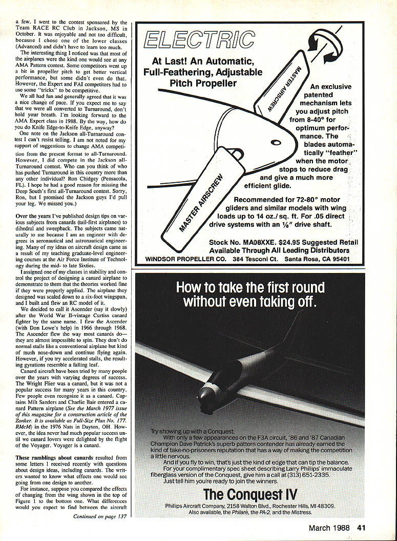
Figure 1. Two wings have equal chords and equal areas. What different characteristics would you expect to find between the airplanes?
Both wings have the same span and chord, so the wing area is the same. For equal-weight airplanes, the wing loadings would be the same. The bottom wing has substantial sweepback, so it would exhibit dihedral effect as the result of the sweepback, and less geometric dihedral would be required.
The aerodynamic center of the top wing is about one-fourth of the wing chord back from the leading edge of the top wing. The aerodynamic center of the bottom (swept) wing is almost at the trailing edge of the root chord. This means that, in order to get the same longitudinal (pitch) and lateral (yaw) characteristics from the two airplanes, the swept-wing design would probably need a longer tail moment and/or larger horizontal and vertical tail surfaces. In addition, the center of gravity of the swept-wing design would be further aft.
These are not all the differences you would expect to find, but the example demonstrates how a relatively simple change in design can cause significant changes to other parts of the airplane.
Rudder designs (Figure 2)
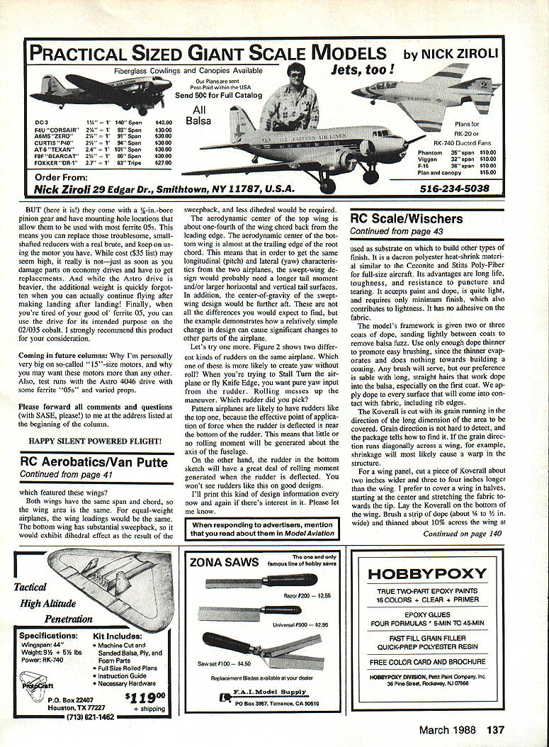
Figure 2 shows two different kinds of rudders on the same airplane. Which one of these is more likely to create yaw without roll? Which one are you trying to create yaw without roll? When you're trying to Stall Turn the airplane or fly Knife Edge, you want pure yaw input from the rudder. Rolling messes up the maneuver.
- Pattern airplanes are likely to have rudders like the top one, because the effective pivot or application of force when the rudder is deflected is near the bottom of the rudder. This means that little or no rolling moment will be generated about the axis of the fuselage.
- On the other hand, the rudder in the bottom sketch will have a great deal of rolling moment generated when deflected. You won't see rudders like this on good designs.
I'll print this kind of design information every now and again if there's interest in it. Please let me know.
Please forward all comments and questions (with SASE, please!) to me at the address listed at the beginning of the column.
HAPPY SILENT-POWERED FLIGHT!
Transcribed from original scans by AI. Minor OCR errors may remain.

