
Radio Control: Sport and Aerobatics
Ron Van Putte 11 Sleepy Oaks Rd. Ft. Walton Beach, FL 32548
Pattern classes — a brief history
Recently I received a letter from Al Seidowski (Cleveland, OH) asking that I continue a light treatment of aerodynamic principles. The name sounded familiar and then it struck me: Al Seidowski was probably responsible for the current AMA Pattern classes. I remember back in the Sixties, when I was a member of the Western Ohio Radio Kontrol Society (WORKS) in Dayton, OH, that Al came to a WORKS club meeting to promote a new style of Pattern competition.
Prior to that time the Pattern classes were organized as Classes 1, 2 and 3 (Novice through Expert):
- Class 1: rudder and throttle only.
- Class 2: rudder, elevator and throttle.
- Class 3: rudder, elevator, aileron and throttle.
Which class you flew was determined by the airplane you flew. Pilots in Classes 1 and 2 had big disadvantages, but once they overcame them they became very good at using limited controls to produce neat maneuvers. A number of those old-timers are still around — for example, Jim Goad (Indy R/C) was one of the better Class 1 fliers, and Bud Atkinson (who currently writes the "Scale" column for Model Airplane News) built the famous Class 2 ship Aristocat, which could produce three axial rolls without ailerons; Bud won the Nats in Class 2 at least once.
Al promoted a Pattern-class system in which all airplanes had three-axis controls while the patterns varied in complexity. He faced stiff resistance — many pilots liked what they had and didn't want to build new airplanes to compete — but his idea dramatically changed the way Pattern is flown. Thanks, Al.
Inverted flight problems and the center of mass
I also received a letter from Conrad Manthey (Memphis, TN) that struck a familiar chord. He described building a Super Kaos .40 that flew great except when inverted: it nosed down toward the ground unless a fair amount of down elevator was held. He tried several fixes, one at a time, with no improvement:
- changing wing incidence (lowering the leading edge at the center to give positive incidence inverted),
- altering engine incidence (adding downthrust when inverted),
- moving the center of gravity aft.
None of those changes helped on his first attempt, and his new Pattern ship shows the same symptoms.
That rang true for me. I had a Phoenix 6 that drove me crazy in maneuvers that required rolling inverted: it would immediately head for the ground unless I used generous down elevator. Three Horizontal Rolls meant continuously "sawing" the elevator; Three Reverse Outside Loops and Slow Rolls were a terror to start. I learned to hide the deficiency, but Don Lowe (a rocket engineer) watched and suggested the center of mass was too far forward. I moved the CG aft and the airplane flew much better. Since then I've flown several ships with the same symptoms and have invariably solved the problem by systematically moving the center of mass aft. On my latest airplane, a T-2A Mk II, I added two long strips of stick-on weights to achieve the desired balance; it now flies inverted fine and lands smoothly.
A few cautions and practical notes:
- Moving the center of mass aft increases pitch sensitivity: trim becomes more critical and elevator effectiveness increases.
- Ensure servos are accurately centered and linkages are solid; otherwise the airplane will be "spooky" in trim, pitching unpredictably.
- Too far aft a CG makes the airplane jumpy — small control inputs produce large pitch changes.
- Move the CG back in small steps and desensitize elevator controls as you go.
- With the correct CG you should need only a tap of down elevator for point rolls and may need little or none for horizontal rolls.
Get the center of mass right and inverted flight becomes much more pleasant.
Vertical tail (fin) effectiveness
A common belief is "there's no such thing as too much tail." That's not true. Too much vertical fin can cause spiral instability. Conversely, too little tail can leave the airplane directionally weak or cause other undesirable behaviors — for example, I once had a fuel-soaked Beechcomber whose tail departed in a dive and produced a very screwy maneuver. There is a happy medium.
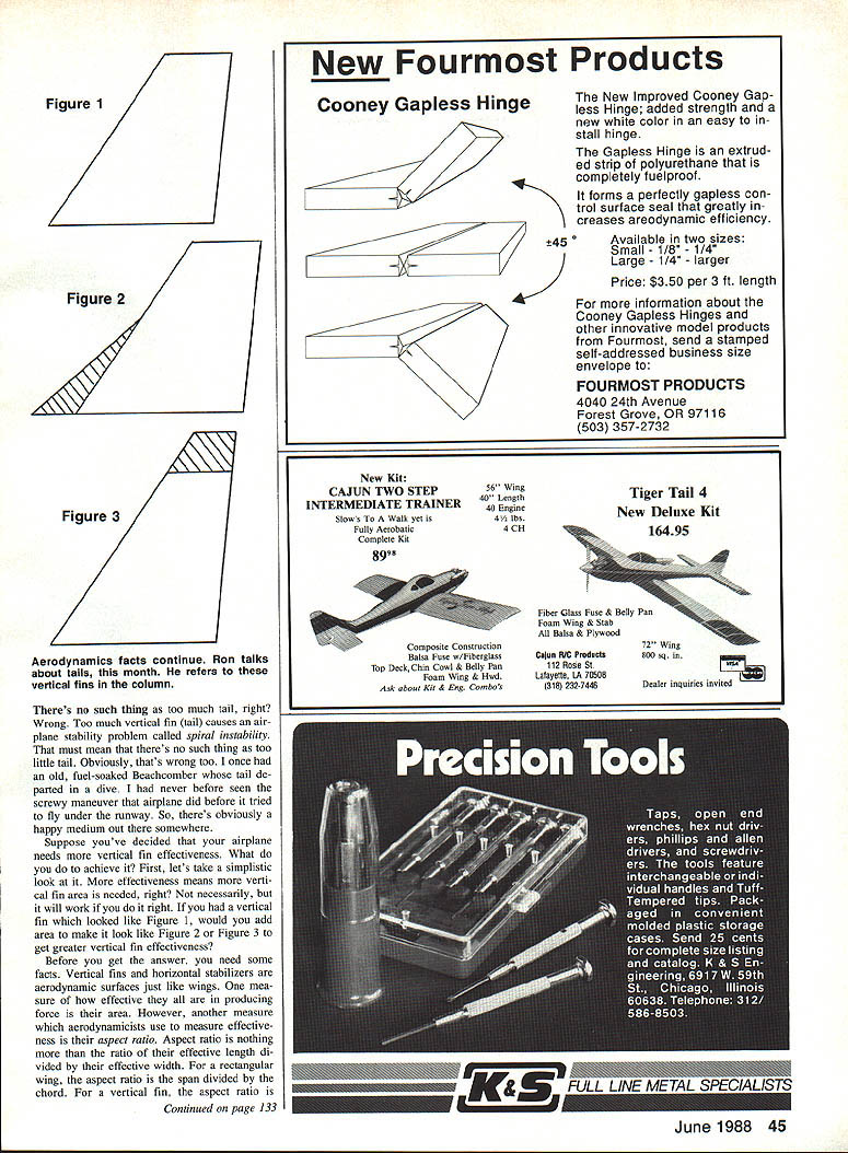
If you decide your airplane needs more vertical fin effectiveness, consider these points:
- Vertical fins and horizontal stabilizers are aerodynamic surfaces like wings. One measure of effectiveness is aspect ratio (span divided by chord for a rectangular planform; span squared divided by area for other planforms). For a vertical fin, the effective aspect ratio is reduced by the fuselage, so a tall, narrow fin will be more effective than a short, deep one for the same area.
- Practical limits exist on fin height because of structural weight, attachment strength at the root, and potential ground-handling problems.
- Increasing fin area will work if done correctly, but there are alternatives: increasing the moment arm (distance from the airplane's center of gravity to the fin's center of pressure) can increase yaw restoring moments without increasing area. Moving the fin aft, adding tip fins or ventral fins are ways to do this.
If possible, prefer a long, slender fin (higher aspect ratio). If that's not feasible, increasing area or increasing moment arm are both effective. As always, make changes in small steps and flight-test between changes.
Ron Van Putte
Transcribed from original scans by AI. Minor OCR errors may remain.

