
Radio Control: Sport and Aerobatics
Ron Van Putte 111 Sleepy Oaks Rd. Ft. Walton Beach, FL 32549
Introduction
The longer I write this column — 13 years and counting — the more I get recurring questions. One of the most common is: "Where do I place the center of gravity on my new plane?" New R/C fliers join the hobby all the time and often haven't read previous columns, so it's time to revisit the center-of-gravity calculation. I’ll aim for a middle ground between excessive mathematics and oversimplification.
Aerodynamic center vs. center of pressure
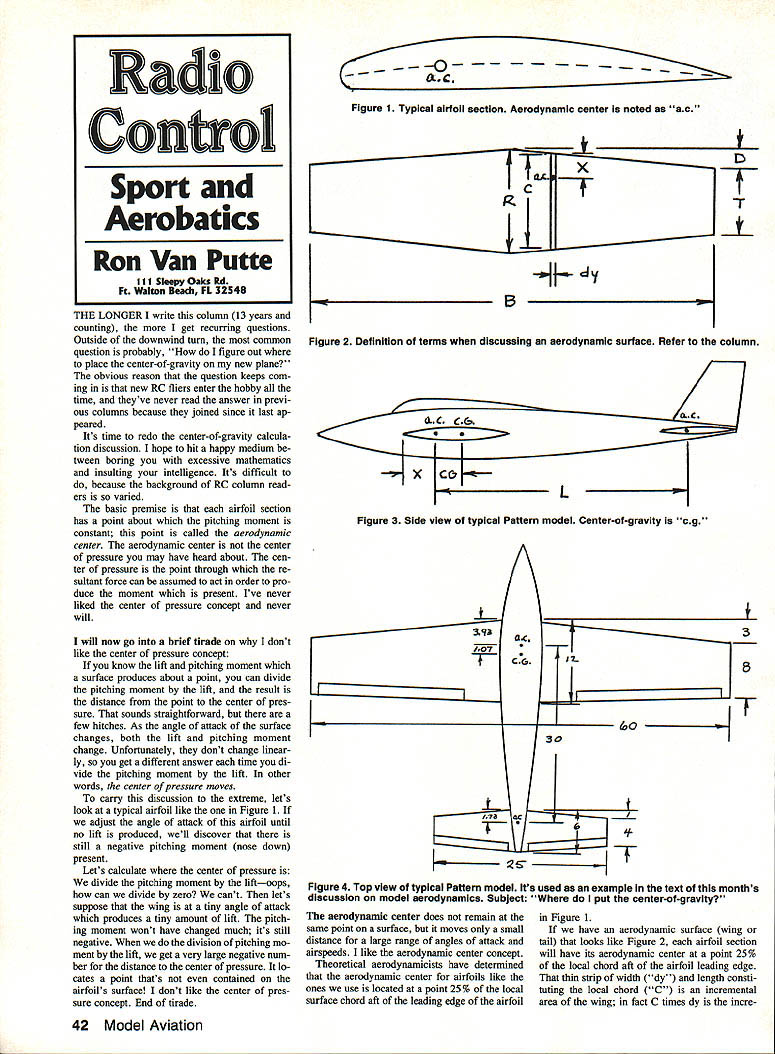
The basic premise: an airfoil section has a point about which the pitching moment is essentially constant. This point is called the aerodynamic center.
You may have heard of the center of pressure — the point through which the resultant aerodynamic force can be assumed to act to produce the measured moment. I don't like the center of pressure concept. The lift and pitching moment change with angle of attack, and they do not change linearly, so the center of pressure moves. In extreme cases (for example, when lift is zero but a pitching moment remains), dividing moment by lift is meaningless or produces a nonsensical location. The aerodynamic center, by contrast, moves only a small amount over a wide range of angles of attack and airspeeds and is therefore a much more useful concept.
Theoretical aerodynamicists have determined that, for the airfoils we typically use, the aerodynamic center is located at 25% (one-quarter) of the local chord measured aft from the leading edge.
Theory and equations
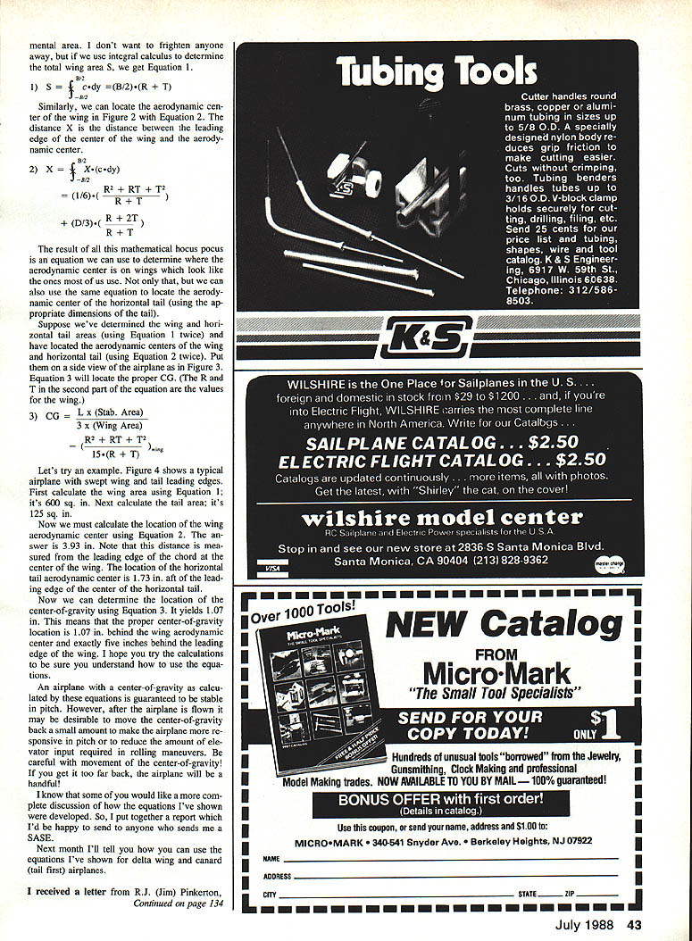
If a wing or horizontal tail is represented as a series of thin strips (each of local chord c and spanwise width dy), the incremental area is c dy. Using calculus you can find total area and the aerodynamic-center centroid:
- Equation 1 — wing (or tail) area:
S = ∫ c dy (integrated over the span)
- Equation 2 — aerodynamic center location (measured from a chosen reference, e.g., the local leading edge position):
x̄ = (1/S) ∫ x c dy (where x is the distance from the chosen leading-edge reference to the local aerodynamic-center strip)
Once you have the wing and horizontal tail aerodynamic centers and areas, you can compute the proper longitudinal center of gravity (CG) for stability with a simple area-weighted average:
- Equation 3 — longitudinal CG (measured relative to the wing aerodynamic center):
X_CG = (X_w S_w + X_t S_t) / (S_w + S_t) (X_w and X_t are the longitudinal positions of the wing and tail aerodynamic centers measured from a common reference)
How to use the equations (step-by-step)
- Determine local chord c(y) along the span and integrate to get total area S using Equation 1 for both wing and horizontal tail.
- Compute the centroid x̄ for each surface using Equation 2 to locate each aerodynamic center relative to your chosen reference.
- Place the aircraft side view geometry on the same reference and use Equation 3 to compute the CG location.
Example
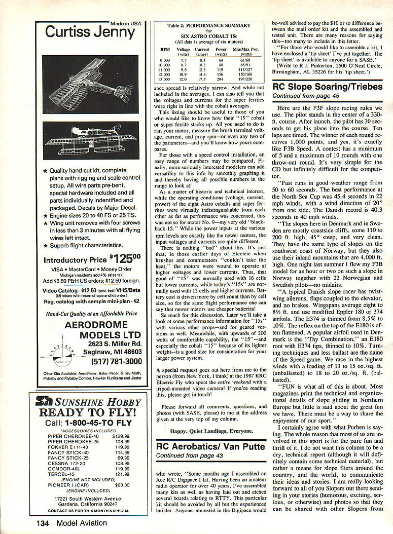
Using a typical airplane with swept leading edges:
- Wing area, S_w = 600 sq. in.
- Horizontal tail area, S_t = 125 sq. in.
- Wing aerodynamic center location (measured from the wing center chord leading edge): X_w = 3.93 in. aft of the wing leading edge center chord.
- Tail aerodynamic center location (measured from the horizontal tail center chord leading edge): X_t = 1.73 in. aft of the tail leading edge center chord.
Using Equation 3 with the appropriate relative positions yields:
- X_CG = 1.07 in. aft of the wing aerodynamic center, which corresponds to exactly 5.00 in. aft of the wing leading edge (measured as described in the example).
I encourage you to try the calculations yourself to ensure you understand how to use the equations.
Practical considerations
An airplane with a CG determined by these equations will be pitch-stable. After flight testing you may want to move the CG slightly aft to make the airplane more responsive in pitch or to reduce elevator input required in rolling maneuvers. Be careful: move the CG too far aft and the airplane will be unstable and difficult to control.
Appendix and next topic
If you'd like a more complete derivation of the equations, I have an appendix available; I'll be happy to send it to anyone who sends a SASE.
Next month I'll explain how to apply these equations to delta-wing and canard (tail-first) airplanes.
Transcribed from original scans by AI. Minor OCR errors may remain.

