
Radio Control: Sport and Aerobatics
Ron Van Putte
111 Sleepy Oaks Rd. Ft. Walton Beach, FL 32548
Last month I included drawings and calculations on how to locate the "proper" center-of-gravity of an airplane. I wrote "proper" because there are various "proper" centers-of-gravity. For example, some centers-of-gravity are so far forward that the airplane will be very stable in pitch — so stable that it would be difficult to maneuver. On the other hand, some centers-of-gravity are so far aft that the airplane is extremely maneuverable. Depending on what is desired, the range of "proper" centers-of-gravity is very broad. My use of "proper" was intended to yield a safe starting point for test flying the airplane. After the initial flights, the center-of-gravity can be moved forward to achieve more pitch stability or aft to get more maneuverability.
Several people wrote to ask what the difference was between center-of-mass and center-of-gravity, since I tend to alternate the terms in this space. Without a long-winded discourse: for our purposes they are the same. Part of my occupational background involved working with the flight mechanics of space vehicles, and there is no such thing as a center-of-gravity of a vehicle in deep space. There is a center-of-mass, and it's the same point whether the vehicle is in space or in the vicinity of Earth. That's why I sometimes use center-of-mass, but you needn't worry about the distinction for our purposes.
This is an introduction to what I promised last month: how to locate the "proper" center-of-gravity of a canard aircraft or a flying-wing aircraft. Please refer to the last column for the drawings; I won't redo them here.
Equations for Canard and Flying-Wing Aircraft
If you are trying to find the proper center-of-gravity of a canard aircraft, the only real difference is that the tail is in front of the wing. You can use the same equations as before to calculate the wing and tail areas and the locations of the aerodynamic centers of the wing and tail. However, when you calculate the location of the proper center-of-gravity, you must change the sign on the "L" term in Equation 3 (because the tail is in front of the wing) and multiply that term by two. (Equation 3 was in the July '88 column.) The result is Equation 4:
4) CG = (2 L × (Stab. Area)) / (3 × (Wing Area)) = (R^2 + R·T + T^2) / (15 * (R + T))
Since both terms in the equation are negative, the proper center-of-gravity location is in front of the wing aerodynamic center by the amount calculated. The reason for multiplying by two is that the wing causes an effect on the tail of a conventional (tail-last) airplane which is not present on a canard airplane unless the tail is very large relative to the wing.
A flying-wing airplane's proper center-of-gravity is easier to calculate because the tail is not present. Simply eliminate the tail-length and tail-area terms. The result is Equation 5:
5) CG = (R^2 + R·T + T^2) / (15 * (R + T))
As before, the remaining term is negative, so the proper center-of-gravity location is in front of the wing aerodynamic center.
Fiesta of Five Flags and the High-Idle Trick
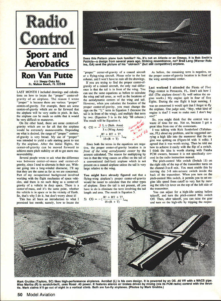
Last weekend I attended the Fiesta of Five Flags contest in Pensacola, FL. Don't ask how I did — the airplane doesn't fly well unless the engine works. My engine quit in four of five flights. During the one flight it kept running, I was so concerned it would quit that I forgot to fly the airplane. One judge said, "Hey, what kind of engine is that? I want to make sure I don't buy one!"
It wasn't a total waste, though, because I got a great idea from one of the contestants. I was talking with Rick Sunderland (Tallahassee, FL) about my problem, and he suggested carrying a high-idle for maneuvering in case the engine starts quitting during maneuvers. He said it would be easy to achieve by flipping a switch.
For Futaba PCM owners this trick is worth sharing because the radio instruction manual specifically covers the pitch-control Mix switch. Notes on the procedure:
- Switch 11 (right side, top) on the transmitter turns the channel-3-to-8 mix on and off. You must enable the 3-to-8 mix actuate switch inside the back of the transmitter.
- The pitch-control Mix switch permits setting the engine idle speed cutoff very fast. Use the Idle-Up lever (top left side of the transmitter) to adjust the high-idle setting before takeoff.
- Turn the pitch-control Mix switch Off for takeoff. After takeoff, you can raise the gear and turn on the high-idle by flipping the respective switches.
- I suggest operating both switches at the same time as a memory aid — turn On/Off high-idle since you rarely forget to raise or lower the landing gear.
Thanks to Rick Sunderland for discovering the trick.
Letters and Feedback
I received a very nice complimentary letter from Larry Miles (Independence, MO). He admitted he was a control-line flier who had "never flown an RC airplane or had much to it." Nevertheless, he said he read my column for the humor: "... seeing as how with increasing age I seem to have more and more appreciation for the lighter side of life, I suspect it's your inclusion of the comic I cherish the most."
Larry's appreciation of the humor in the column is right on; it's part of my outlook on life. I hope readers understand and appreciate the humor that's part of me.
Larry also mused about Duke Fox's efforts in noise reduction by using a plastic fuel tank as an after-muffler. He suspects that what Duke "had done in addition to providing additional surfaces for the sound waves to bounce off was to provide a soft, sound-absorbing surface (the plastic tank) for the various molecules to give their vibrational energy to in much the same way the interiors of high-fidelity enclosures are lined with similar materials. The same goes for automotive glass-pack mufflers, perhaps small arms mufflers (silencers) to deaden their sounds."
Consequently, Larry believes that "a model engine muffler whose interior was coated with some of the high-temperature silicone glues might be a good starting point to making a more effective single-unit muffler without the need for the plastic tank after-muffler." Maybe he has a point; others have tried similar ideas.
Perry Rose (51 Plainfield Road, Moosup, CT 06354) wrote to describe his sound-reduction experiments. He read that wrapping a tuned pipe could deaden the sharp, tinny sound. Using a Radio Shack sound meter, he checked an OS .61 FSR ABC turning a Rev-Up 11 x 8 at 12,700 rpm and measured 97–98 dBA at 10 ft.
- He installed an 11 x 9 Zinger, stretched the pipe a couple of inches, and got 11,500 rpm and 94 dBA.
- He then put a rubber sleeve (which looks like a piece of bicycle inner tube) on the MACS pipe and repeated the test. The 11 x 8 turned faster (maybe due to needle adjustment) at 12,900 rpm and measured 96–97 dBA. The 11 x 9 turned at 11,500 rpm and measured 92–93 dBA. The whole deal took a half hour. His pipe is underwing and exposed; the rubber didn't burn or melt during the test.
Perry described getting the tubing on the pipe by putting Vaseline on the pipe and working the tubing on from the front end until it covered the whole pipe. "It took a solid five minutes of work to get on." If interested, Perry will send one of the sleeves for $3.50, S&H included.
Plans Request
Bill Hintz (711 E. Northridge Ave., Glendora, CA 91740) wrote asking if plans for the Snap Hog, the Astro Hog, and the Rudder Bug are available. I couldn't come up with a source. If any reader can, please drop Bill a note.
Note: Sig released a newly engineered kit of the Astro Hog recently.
Transcribed from original scans by AI. Minor OCR errors may remain.

