
Radio Control: Sport and Aerobatics
Ron Van Putte 111 Sleepy Oaks Rd. Ft. Walton Beach, FL 32548
Introduction
Two months ago I wrote about locating the proper center-of-gravity for a conventional airplane. Last month I extended the coverage to canard airplanes and flying-wing airplanes. I sat back thinking the subject was done. Not so. In addition to requests for more information, the mailbag has been full of lots of good questions. Rather than sending answers only to the questioners, I decided to include one of the better questions and my answer here.
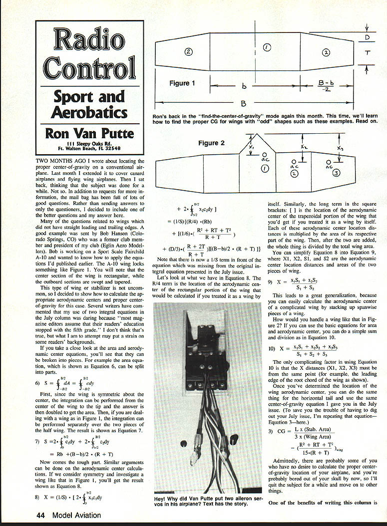
Many of the questions related to wings that did not have straight leading and trailing edges. A good example was sent by Bob Hanson (Colorado Springs, CO), a former club member and president of my club (Eglin Aero Modelers). Bob is working on a Sport Scale Fairchild A-10 and wanted to know how to apply the equations I’d published earlier. The A-10 wing looks something like Figure 1. You will note that the center section of the wing is rectangular, while the outboard sections are swept and tapered.
This type of wing or stabilizer is not uncommon, so I decided to show how to calculate the appropriate aerodynamic centers and the proper center-of-gravity for this case. Several writers have commented that my use of two integral equations in the July column was daring because "most magazine editors assume that their readers' education stopped with the fifth grade." I don't think that's true, but what I am attempting may put a strain on some readers' backgrounds.
Area and aerodynamic center — breaking the integrals into pieces
If you take a close look at the area and aerodynamic-center equations, you'll see that they can be broken into pieces. For example, the area equation, shown as Equation 6, can be split into parts.
- 6) S = ∫_{-b/2}^{b/2} c dy
First, since the wing is symmetric about the center, the integration can be performed from the center of the wing to the tip and the answer is then doubled to get the area. Then, if you are dealing with a wing as in Figure 1, the integration can be performed separately over the two pieces of the half wing. The result is shown as Equation 7.
- 7) S = 2 { ∫_{0}^{b/2} c dy } = Rb + (B - b)/2 · (R + T)
Similar arguments can be applied to the aerodynamic-center calculations. If we consider symmetry and investigate a wing like that in Figure 1, you'll get the result shown as Equation 8.
- 8) X = (1/S) [ 2 ∫_{0}^{b/2} x c dy ]
Note the 1/S term in front of the equation, which normalizes the integrated moment to give the mean location. The R/4 term is the location of the aerodynamic center of the rectangular portion of the wing that would be calculated if you treated it as a wing by itself. Similarly, the longer term in the square brackets is the location of the aerodynamic center of the trapezoidal portion of the wing that you'd get if you treated it as a wing by itself. Each of these aerodynamic-center location distances is multiplied by the respective area of that part of the wing. After the two are added, the whole thing is divided by the total wing area.
You can simplify Equation 8 into Equation 9, where X1, X2, S1, and S2 are the aerodynamic-center location distances and areas of the two pieces of wing:
- 9) X = (X1·S1 + X2·S2) / (S1 + S2)
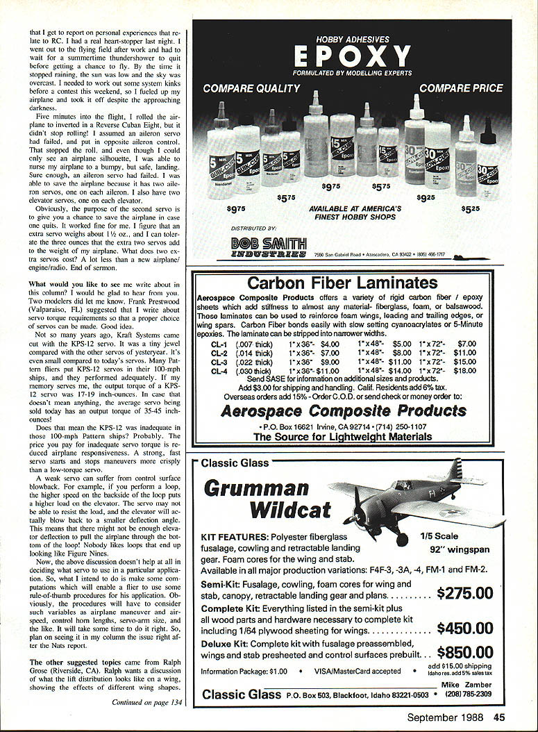
This leads to a useful generalization: you can calculate the aerodynamic center of a complicated wing by stacking up spanwise pieces. For a wing like Figure 2 you would use the same approach:
- 10) X = (X1·S1 + X2·S2 + X3·S3) / (S1 + S2 + S3)
Only one complicating factor in using Equation 10 is that the X distances (X1, X2, X3 ...) must be measured from the same reference point (for example, the leading edge of the root chord of the wing as shown). Once you've determined the location of the wing aerodynamic center, you can do the same thing for the horizontal tail and use the same center-of-gravity equation I gave you in the July issue. (To save you the trouble of digging out your July issue, I'm repeating that equation here.)
- 3) CG = [ L·(Stab. Area)·(x_stab) + (Wing moment terms) ] / (Stab. Area + Wing Area)
Admittedly, some of you have no desire to calculate the proper center-of-gravity location for your airplane, and you may be bored by now, so I'll quit the subject for a while and move on to other things.
Personal experiences — why redundancy can save your airplane
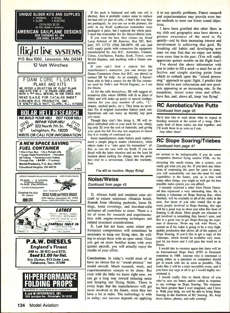
One of the benefits of writing this column is that I get reports of personal experiences related to R/C. A real heart-stopper happened last night. I went out to the flying field after work to wait out a summertime thundershower. It quit before I had a chance to fly, so I used the time to work out some system kinks before a contest weekend. I fueled up the airplane and took off despite approaching darkness. Five minutes into the flight the airplane rolled inverted. In a reverse Cuban eight it didn't stop rolling. I assumed an aileron servo had failed and put in opposite aileron control. The roll stopped; though I could only see the airplane's silhouette I was able to nurse the airplane back for a bumpy, safe landing. Sure enough, an aileron servo had failed. I was able to save the airplane because I had two aileron servos.
Obviously, the purpose of the second servo is to give you a chance to save the airplane in case one quits. It worked fine for me. I figure that an extra servo weighs about 1/2 oz., and I can tolerate the three ounces that the extra two servos add to the weight of my airplane. What do two extra servos cost? Less than a new airplane/engine/radio. End of sermon.
Upcoming topics: servo torque and lift distribution
What would you like to see me write about in this column? I would be glad to hear from you. Two modelers did let me know. Frank Prestwood (Valparaiso, FL) suggests that I write about servo-torque requirements so that a proper choice of servos can be made. Good idea.
Not so many years ago, Kraft Systems came out with the KPS-12 servo. It was a tiny jewel compared with the servos of yesteryear. Many pattern fliers put KPS-12 servos in their 100-inch ships, and they performed adequately. If my memory serves me, the output torque of a KPS-12 servo is 17–19 inch-ounces. In case that doesn't mean anything, the average servo being sold today has an output torque of 35–45 inch-ounces!
Does that mean the KPS-12 was inadequate in those 100-inch pattern ships? Probably. The price you pay for inadequate servo torque is reduced airplane responsiveness. A strong, fast servo starts and stops maneuvers more crisply than a low-torque servo.
A weak servo can suffer from control-surface blowback. For example, when you perform a loop, the higher speed on the backside of the loop puts a higher load on the elevator. The servo may not be able to resist the load, and the elevator will actually blow back to a smaller deflection angle. This means there might not be enough elevator deflection to pull the airplane through the bottom of the loop. Nobody likes loops that end up looking like figure-nines.
The above discussion doesn't tell you exactly what servo to use in a particular application. What I intend to do is make some computations that will enable a flier to use rule-of-thumb procedures for his application. Obviously, the procedures will have to consider variables such as airplane maneuver and desired speed, control-horn lengths, servo-arm size, and the like. It will take some time to do it right, so plan on seeing it in my column in the issue right after the Nats report.
The other suggested topic came from Ralph Grosse (Riverside, CA). Ralph wants a discussion of what the lift distribution looks like on a wing, showing the effects of different loadings, and related material. Send me your suggestions and questions—I'll try to cover them in upcoming columns.
Ron Van Putte III 111 Sleepy Oaks Rd. Ft. Walton Beach, FL 32548
Transcribed from original scans by AI. Minor OCR errors may remain.

