
Radio Control: Sport and Aerobatics
Ron Van Putte 111 Sleepy Oaks Rd. Ft. Walton Beach, FL 32548
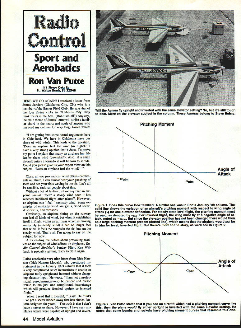
Here we go again!
I received a letter from James Sanders (Oklahoma City, OK), a member of the Baxter Field Club. He says that of the four flying clubs in Oklahoma City, they think theirs is the best. (Don't we all?) The main theme of James's letter will strike a familiar chord in the hearts and souls of anyone who has read my column for very long. James wrote:
"I am getting into some heated arguments here in Okie land. We here in Oklahoma have our share of wild winds. This leads to the question, 'Does an airplane feel the wind (in flight)?' I have a very strong opinion that it does. To prove my point I explain that many an airplane has fallen due to wind shear (downdraft). Also, if a small aircraft enters a tornado it will be torn to shreds. Could you please give us your expert view on this subject, 'Does an airplane feel the wind?'"
Okay, all you pro-and-con wind-effects combatants out there, I can almost hear your gnashing of teeth and see your fists waving in the air. Let's all be sensible, rational people about this.
On wind effects
Without a lot of fanfare, let me say that an airplane cannot "feel" a steady wind once it has reached stabilized flight after takeoff. However, an airplane can "feel" unsteady wind. Some examples of unsteady wind are gusts, wind shear, dust devils, and tornadoes.
Obviously, an airplane sitting on the runway can feel all kinds of wind, but when it establishes itself in flight within an air mass that is moving uniformly (a steady wind) it can no longer feel that wind. It feels the bumps in the air, but not the steady wind. That's all I'm going to say on the subject for now.
After chiding me before about provoking readers on the subject of wind effects on airplanes, Radio Control Modeler's Sunday Flier, Ken Willard, is probably getting ready to do it again.
Pitching moment and trim
I also received a very nice letter from Dick Hanson (Dick Hanson Models), who questioned my statement in the January 1989 column that it took a very complicated set of interactions to enable an airplane to fly upright and inverted without changing elevator input. He wrote, "I am not a professional aerodynamicist—so be patient and please relate to me just one complicated interchange which will produce identical upright or inverted flight."
When I read that I thought, "Blast! He thinks I've got a secret hidden away that has eluded Pattern designers for years!" The truth is that I don't have any secret to share. However, I have seen airplanes that were capable of upright and inverted flight with the same elevator input. Does this mean the airplanes are great Pattern designs? In general, no. Nevertheless, I want to show what must have happened to enable airplanes to trim upright and inverted with the same elevator input.
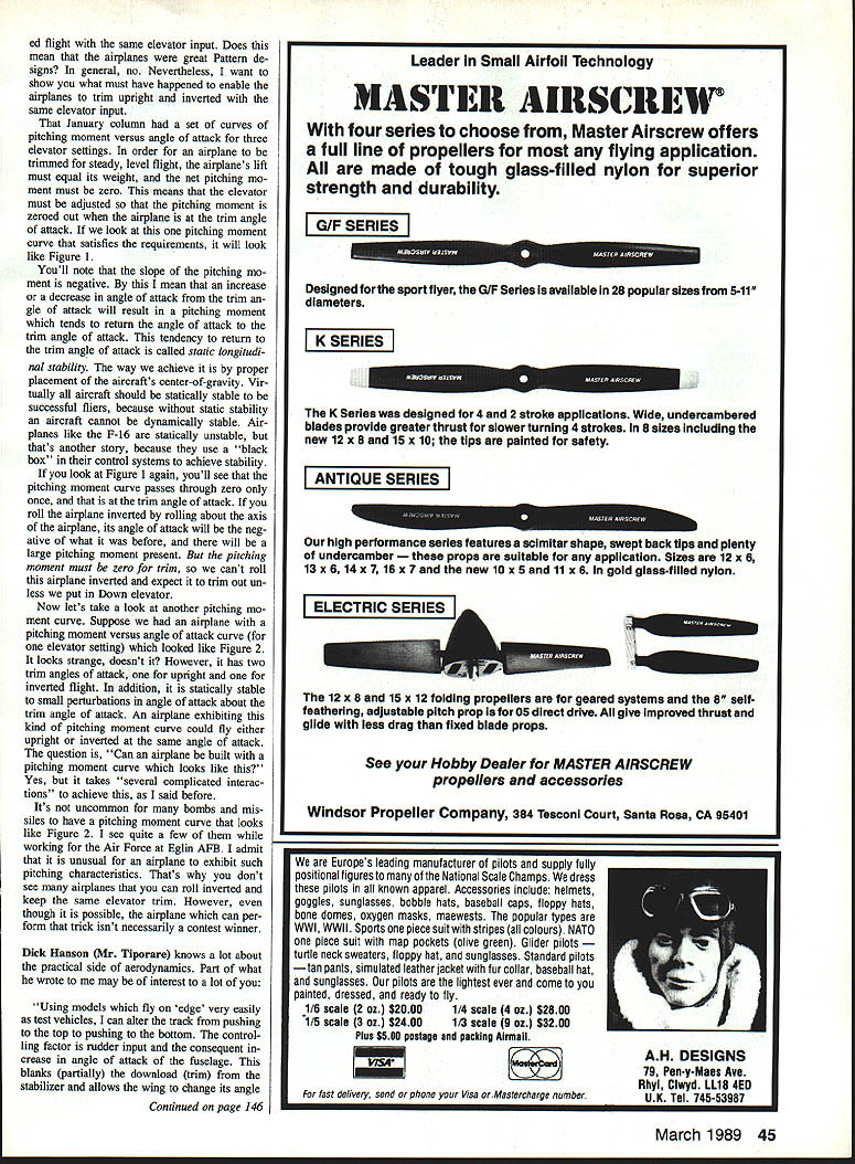
In the January column I set curves of pitching moment versus angle of attack for three elevator settings. In order for an airplane to trim for steady level flight, the airplane's lift must equal its weight and the net pitching moment must be zero. This means the elevator must be adjusted so the pitching moment is zeroed out. The airplane trim angle of attack that satisfies these requirements will look like Figure 1. You'll note the slope of the pitching moment curve is negative; this means an increase in angle of attack will result in a pitching moment that tends to return the angle of attack to the trim angle. This tendency to return to the trim angle of attack is called static longitudinal stability.
One way to achieve proper handling is by placement of the aircraft's center of gravity. Virtually all aircraft should be statically stable to be successful fliers because if an aircraft is not statically stable it cannot be easily flown. Airplanes like the F-16 are statically unstable—that's another story because they use black-box control systems to achieve stability.
Look at Figure 1 again; you'll see the pitching moment curve passes through zero once at the trim angle of attack. If you roll the airplane inverted, rolling about the longitudinal axis, the airplane's angle of attack becomes negative, and the pitching moment for the same elevator setting will generally not be zero.
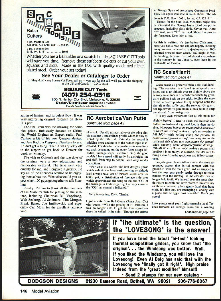
Now let's take a look at another pitching moment curve. Suppose we had an airplane with a pitching moment versus angle of attack curve (for one elevator setting) that looked like Figure 2. It looks strange, doesn't it? However, it has two trim angles of attack, one for upright and one for inverted flight. In addition, it is statically stable to small perturbations in angle of attack about the trim angles. An airplane exhibiting this kind of pitching moment curve could fly either upright or inverted at the same elevator setting. The question is, "Can an airplane be built with a pitching moment curve which looks like this?" Yes, but it takes several complicated interactions to achieve this, as I said before.
It's not uncommon for many bombs and missiles to have a pitching moment curve that looks like Figure 2. I cited a few of them when working for the Air Force at Eglin AFB. I admit that it is unusual for an airplane to exhibit such pitching characteristics. That's why you don't see many airplanes that you can roll inverted and keep the same elevator trim. However, even though it's possible, the airplane that can perform that trick isn't necessarily a contest winner.
Dick Hanson's practical notes
Dick Hanson (Mr. Tiporan?) knows a lot about the practical side of aerodynamics. Part of what he wrote may be of interest to a lot of you:
"Using models which fly on 'edge' very easily is not the test. I can alter the trim from pushing in the top to pushing to the bottom. The controlling factor is rudder input and the consequent increase in angle of attack of the fuselage. This blanks, partially, the downwash from the stabilizer and allows the wing to change its angle of attack. Usually (almost always) the wing simply assumes a streamlined profile which is only affected by the dihedral. Naturally the model is skidding more and more as the rudder input is increased. The dihedral now produces its own forces, and, depending on the other force setups (dihedral, fuselage shape, stabilizer, etc.), the models I have tested will easily fly a straight line and shift from 'top to bottom' with only rudder corrections."
For what it's worth: the best designs (those which exhibit the least corkscrewing or altitude loss) always have lots of forward lateral area; or better put, a distribution of fuselage side area that approximates the wing so that the CG of the fuselage in knife-edge flight is very close to the CG as normally indicated.
Very interesting, Dick. Thanks.
Materials: "White Skin" styrofoam
I got a note from Bud Owens (Santa Ana, CA) who wrote, "With the passing of Hi Johnson, I was no longer able to get the thin styrofoam sheets he called 'white skin.' Through the efforts of George Sparr of Aerospace Composite Products, it is again available in 24-in. sheets. The address is P.O. Box 16621, Irvine, CA 92714."
Thanks for the hint, Bud. Modelers might also be interested that George has a lot of composite products, including:
- glass cloth
- Kevlar mat
- Aero T-mat
- Aero K-mat
- and others
Drop him a line.
Closing
As this is written, it's just before Christmas. I hope you had a nice one and are happily building away on—or otherwise enjoying—your RC-oriented presents from Santa. You might as well be building, because it's cold almost everywhere in the country in late January, even here in the panhandle of Florida.
Transcribed from original scans by AI. Minor OCR errors may remain.

