
Radio Control: Sport and Aerobatics
Author
Ron Van Putte 111 Sleepy Oaks Rd. Ft. Walton Beach, FL 32548
Hints and adhesives
Let me pass on a few hints before getting to the meat of this article. The first two involve adhesives.
I've been in the hobby long enough that I can remember when everyone used Ambroid (didn't it smell great?). The water-soluble glues like Tite‑Bond and Wilhold were big improvements, and so were the cyanoacrylates like Hot Stuff, Jet Zap, etc. The same is true of the epoxies and contact cements — they all work great in their own way.
There are some adhesives that work better than others in specific applications. One of the most difficult applications, in my book, is adhering servo rails to the sides of polyester or epoxy fiberglass fuselages. I always worried about servo rails popping loose from the fuselage sides in hard landings and violent maneuvers. My fears were justified — sometimes they did pop loose. I used epoxies and cyanoacrylates, but nothing was satisfactory. Then I tried Wilhold R/C-56 adhesive, and it works. It has a combination of flexibility and tenacity that makes it ideal for attaching wood to fiberglass. I gave it some pretty severe tests (including an airplane crash) and couldn't get it to pull the rails loose from the fuselage sides.
R/C-56 is white in the bottle, but it dries clear. It is easy to clean up with a wet rag when it is wet, but nothing seems to touch it when it is dry. I also use it to install bulkheads in fiberglass fuselages, to install hinges, and to attach canopies to the fuselage. It works great.
Do you ever worry that the wing bolts will pull the threads right out of the plywood they screw into? Me, too. Then I discovered that you can trickle a little cyanoacrylate down the threads in the plywood and make them many times stronger. After applying the adhesive and allowing it to set, I usually rethread the hole to remove the hardened wood fuzz and clean up the threads. You'll break the nylon bolts before pulling them out.
Sanding tip
A good-looking finish requires a lot of sanding. After applying primer, sand. After the base coat, sand. After subsequent coats, sand. As I said — a lot of sanding. Sanding is tough work; the dust goes everywhere, especially after the primer coat. So I've resorted to alcohol. No, not for drinking — I'm talking about wetting the surface to be sanded.
I use rubbing alcohol on the surface I'm sanding. Alcohol must be used with wet-or-dry sandpaper; it holds down the sanding dust and really shortens sanding time. Use a plastic laboratory bottle to squirt some alcohol on the surface and sand until just before the surface dries up. Rub off the slimy mess with a soft cloth. I think alcohol partially dissolves the finish on newly painted surfaces and epoxies — that's what makes sanding go much faster.
Aerodynamic center — theory and techniques
I've gotten enough letters from modelers asking about locating the aerodynamic center of a wing that I think there's enough general interest to warrant the following discussion. The key information that makes the calculations work can be broken into pieces. Each piece contributes its part; the total aerodynamic inputs can be calculated by adding up the effects of the parts. There are limitations to the theory because of edge effects at the places pieces join, but if the wing has a reasonably high aspect ratio (approximately the ratio of wing span to chord), the theory works very well.
An airfoil section has an aerodynamic center. The aerodynamic center is the point about which the pitching moment produced by the air flowing over the airfoil is independent of angle of attack. It seems unlikely such a location exists, does it? An airfoil's aerodynamic center is located at the point 25% chord back from the leading edge.
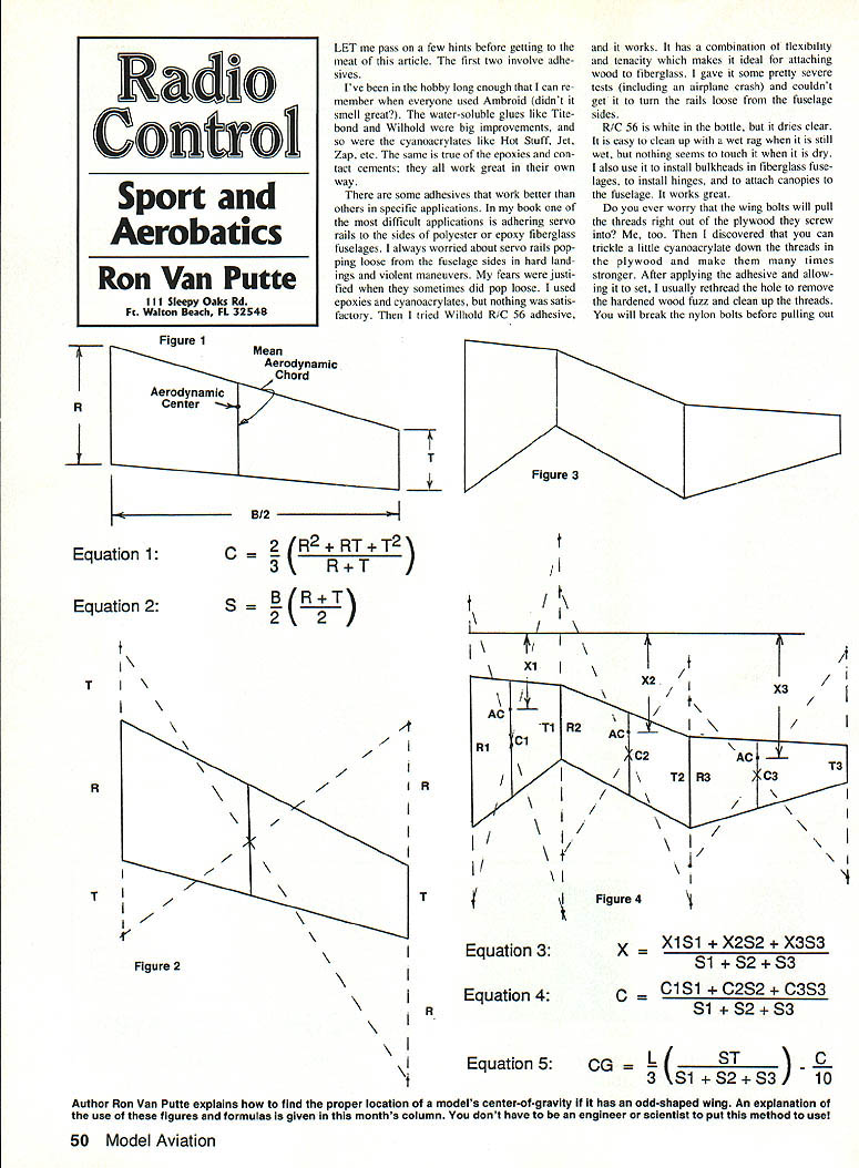
We won't show the integral calculus equation determining the location of the aerodynamic center because the Model Aviation staff has fits trying to get such equations into the typesetting machine. Suffice to say, the aerodynamic center can be calculated as the 25% point of the mean aerodynamic chord (the mean aerodynamic chord is also called the MAC). Sometimes a fictitious chord (a rectangular wing) would produce the same forces and moments as the actual wing. For a wing like Figure 1, the mean aerodynamic chord is calculated by Equation 1.
Figure 1 also shows what the wing's mean aerodynamic chord looks like and where it is located on the wing. You'll note that it's not at the midpoint of the wing; it is not the mean (average) chord.
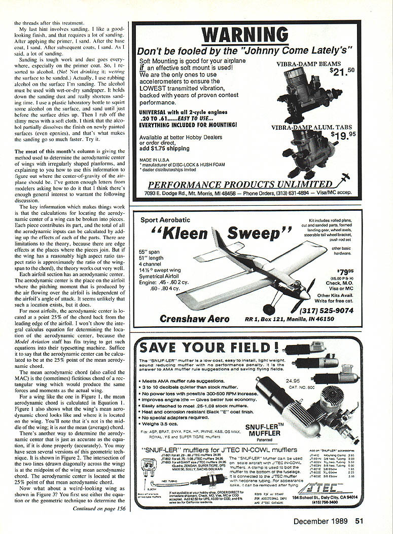
There's another way to determine the aerodynamic center that is just as accurate as the integral calculus method, if it is done properly. You may have seen several versions of this geometric technique. It is shown in Figure 2. The intersection of the two lines (drawn diagonally across the wing) is at the midpoint of the wing mean aerodynamic chord. The aerodynamic center is located at the 25% point of that mean aerodynamic chord.
Irregular or multi-panel wings
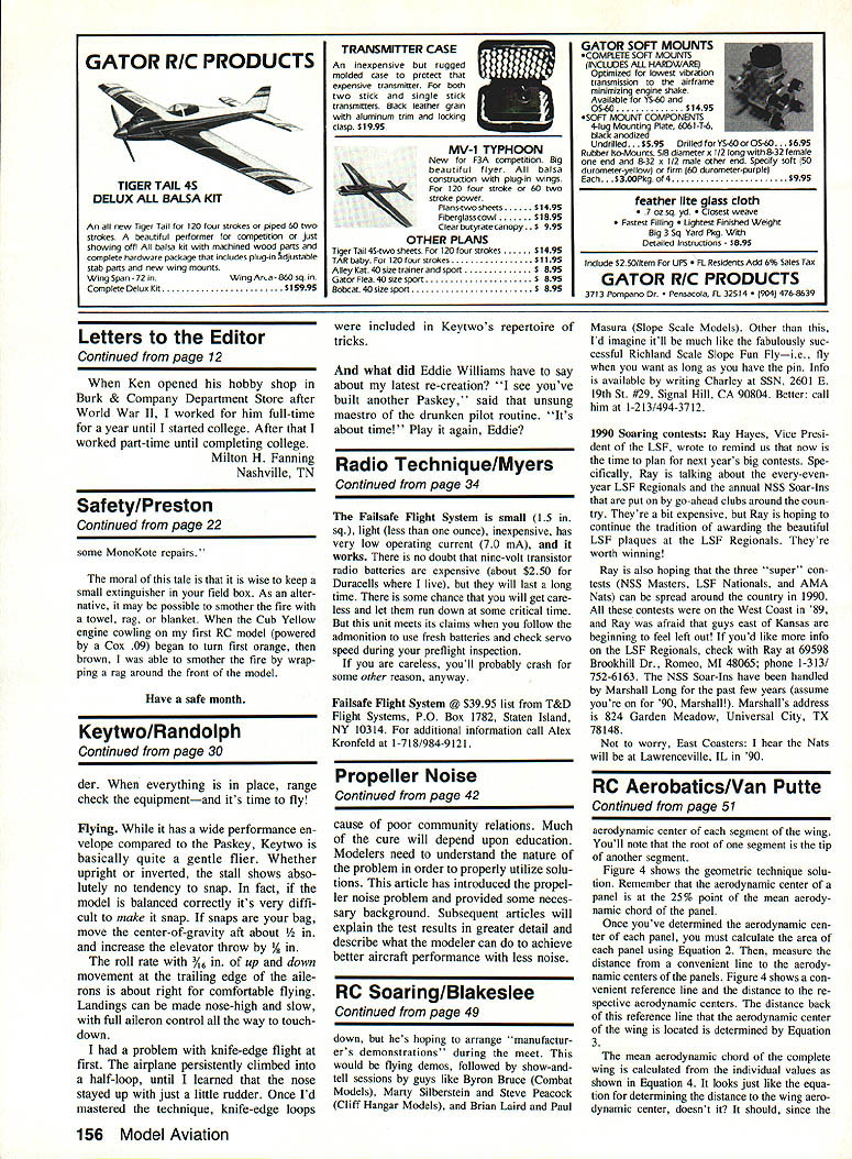
Now what about a weird-looking wing as shown in Figure 3? First use either the equation or the geometric technique to determine the mean aerodynamic chord for each piece of the wing. The wing is then broken into panels, and each panel contributes its part.
Calculate the area and the location of the mean aerodynamic chord for each panel, multiply each panel's area by the location of its mean chord to obtain the moment about a reference line, sum the moments of all the panels, and divide by the total wing area to obtain the location of the wing's mean aerodynamic chord. The aerodynamic center will be at the 25% point of this mean aerodynamic chord.
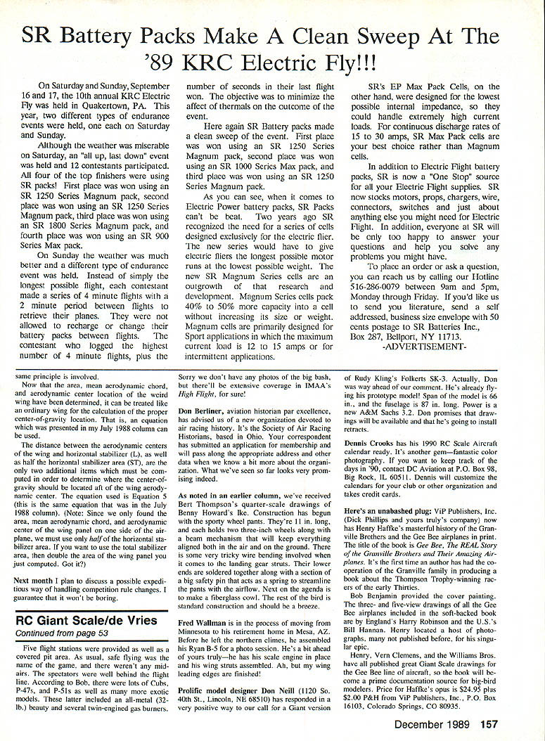
Figure 4 shows the geometric technique solution. Remember that the aerodynamic center of a panel is at the 25% point of the mean aerodynamic chord of that panel.
Once you've determined the aerodynamic center of each panel, you must calculate the area of each panel using Equation 2. Then measure the distance from a convenient reference (for the whole wing) to the aerodynamic center of each panel. Figure 4 shows a convenient reference line and the distances to the respective aerodynamic centers.
The distance back from this reference line to the aerodynamic center of the whole wing is determined by Equation 3.
The mean aerodynamic chord of the complete wing is calculated from the individual values as shown in Equation 4. It looks just like the equation for determining the distance to the wing aerodynamic center — it should, since the mean aerodynamic chord is derived from the same panel areas and chord distances; the same principle is involved.
Center-of-gravity considerations
Now that the area, mean aerodynamic chord, and aerodynamic center location of the wing have been determined, the wing can be treated like an ordinary wing for calculation of the proper center-of-gravity (CG) location. An equation which was presented in my July 1988 column can be used.
The distance between the aerodynamic centers of the wing and horizontal stabilizer (L), as well as half the horizontal stabilizer area (ST), are the only two additional items that must be computed in order to determine where the center-of-gravity should be located aft of the wing aerodynamic center. The equation used is Equation 5 (this is the same equation that was in the July 1988 column).
(Note: Since we only found the area, mean aerodynamic chord, and aerodynamic center of the wing and one side of the airplane, we must use only half of the horizontal stabilizer area. If you want to use the total stabilizer area, then double the area of the wing panel you just computed.)
Closing
Next month I plan to discuss a possible expeditious way of handling competition rule changes. I guarantee that it won't be boring.
Transcribed from original scans by AI. Minor OCR errors may remain.

