
Radio Control: Sport/Aerobatics
Ron Van Putte
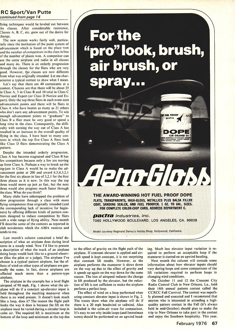
THE LATE Jim Kirkland was inducted into the AMA Hall of Fame at a banquet held in his honor on October 15 at Fort Walton Beach, Fla. More than 50 Eglin Aero Modellers and their wives witnessed the presentation of the Hall of Fame plaque to Jim's widow, Mignon Kirkland Hendrix, by AMA President, John Clemens. Several of Jim's personal friends, Bill Grigsby, Don Lemen and Frank Prestwood, shared the head table with Jim's widow. John Clemens and club president, Dick McGraw, who had arranged the entire affair. It was a proud night for District 5 and the rest of the Academy of Model Aeronautics.
Many people who complain about the current pattern events don't realize the changes that have taken place in RC pattern competition over the years. The original pattern was very simple because the airplane/radio system combinations were also very simple and unreliable. Often the winner in a contest was the contestant who was able to fly a complete flight during the contest. As radio equipment was made more complex and more reliable, the pattern developed to the old Class I, II and III patterns. The I, II and III being the number of axes of control the radio would operate. Class I was called Rudder-Only and the early Class I airplanes were controlled by only the rudder. Later Class I airplanes had both rudder and throttle control.
The really proficient Class I pilots could perform many maneuvers which might be considered impossible by today's rudder-only pilots. The good Class I pilots were very good and that became a problem. When a pilot became proficient in the class he usually stayed there and became better. He and others like him won every contest, so the beginning competition pilot had no place to go.
The same situation characterized Class II competition to a lesser extent. The airplanes were limited to two axes of control, rudder and elevator, plus throttle, and the pilots who developed the techniques to perform the maneuvers, regardless of the aircraft limitations, generally stayed in the same class.
A stagnant situation developed in which the best fliers kept getting better and the beginner didn't have the incentive to enter into competition because every event was dominated by experts. Many people began to suggest changes in the pattern events to provide competition based on orderly progression through all the classes for fliers who consistently won contests. The people who were winning the old Class I and II events opposed such a change because it meant that they would have to move to the next class very quickly and would be forced to buy new radios and airplanes. An even more significant objection was that the hard-earned techniques which made the winners in their classes wouldn't help them much in a new class.
It was obvious that a change would have to be made in competition which not only provided for a progression based on flying competence, but one which also included changes in the kinds of airplanes and radio equipment which would be permitted to be used in the various classes, such that differences in radios, airplanes and flying techniques would be leveled out between classes. After considerable resistance the Classes B, C, etc., grew out of the desire for change.
The new system works fairly well, particularly since the institution of a point system for advancement based on place won and number of competitors in the class in lieu of number of places won. A competitor can use the same airplane and radio in the various classes, and the orderly progression through classes provides for advancement based on flying competence.
However, classes are now different from what was originally intended. Let me characterize a typical contest to show what I mean. Let's say 40 contestants at a contest. Chances are there will be about 25 in Class B, 5 in Class A, and 10 total in Class C and Class D (Novice-Expert). Only the top three fliers in an event earn advancement points. The three fliers in Class B who have beaten 21 others don't earn advancement points. To win enough advancement points to graduate, a Class B flier must be very good and spend a long time in the class. Consequently, the difficulty of earning one's way out of Class B has resulted in an increase in the overall quality of flying in that class. The top five Class B fliers often look like Class A fliers, demonstrating the Class A pattern. Despite the intended orderly progression. Class A has become stagnated and Class B has few competitors because only a few are moving up from Class A. Perhaps a way to break up the log‑jam in Class A would be to make the advancement point at 200 and award 6, 5, 4, 3, 2, 1 for the first six places in lieu of 3, 2, 1 for the first three places as it is now. In this way the top three would move up just as fast, but the next three would also progress much faster through the class. What do you think?
Many clubs have sidestepped the problem of slow progression through a class with more flying competence than originally intended (and the corresponding lack of incentive for beginners) by offering different kinds of pattern contests designed to induce competition by fliers with a wide range of flying ability. Next month I'll describe some of the contests as reported in club newsletters which the AMA receives and sends out.
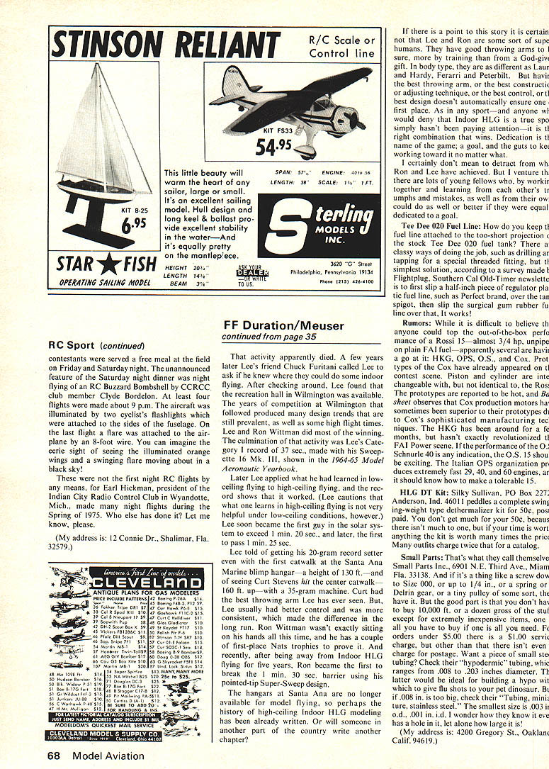
Last month's column contained a brief description of what an airplane does during level turns in a steady wind. Now I'd like to present a description of what the track of an airplane doing loops would look like to a ground observer (like the pilot or a judge). The airplane I've chosen is a typical pattern airplane, but the effects of wind on other types of airplanes are generally the same. In fact, slower airplanes are affected much more than a pattern‑type airplane.
The airplane in the example has a level flight airspeed of 90 mph. Fig. 1 shows what the airplane will do if a constant up‑elevator input is held throughout the resulting maneuver when there is no wind present. It doesn't look much like a loop, does it? The reason the flight path looks the way it does is because the lift on the airplane must be varied during a circular loop in calm air. The required lift is maximum at the bottom of the loop and minimum at the top due to the effect of gravity on the flight path of the airplane. If constant elevator is applied and airspeed is kept constant, it is not surprising that constant lift results. However, as the airplane performs the maneuver it slows down on the way up due to the effect of gravity and it speeds up again on the way down for the same reason. The loss of airspeed reduces the change in lift produced by the elevator, but the reduction of lift is not sufficient to make the airplane perform a perfect loop.
The effect of wind on a loop performed when the constant elevator input is shown in Fig. 2. The traces show what the airplane will do if there is a 20 mph headwind or tailwind. Also included is the calm‑air trace for comparison. It's easy to see why inside loops (and Immelman turns) should be performed on an upwind heading. Much less elevator input variation is required to perform an acceptable loop if the maneuver is started into an upwind heading.
Next month the column will contain some information about how elevator inputs should vary during loops and some comparisons of the lift variations required to perform loops in changing wind conditions.
On October 11 and 12 the Crescent City Radio Control Club in New Orleans, La., held their 14th annual pattern contest called the CCRC Fall Carnival. The contest was superbly planned and executed and I recommend that anyone who is interested in attending a high quality pattern contest in the Fall (it's always held in mid‑October) should plan to make the trip to New Orleans to take part in the contest and enjoy the Southern hospitality. This year,
RC Sport (continued)
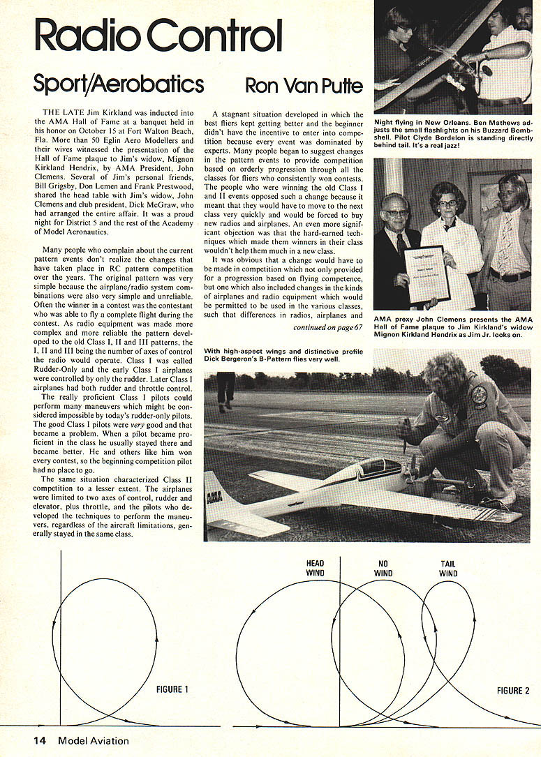
contestants were served a free meal at the field on Friday and Saturday night. The unannounced feature of the Saturday night dinner was night flying of an RC Buzzard Bombshell by CCRC club member Clyde Bordelon. At least four flights were made about 9 p.m. The aircraft was illuminated by two cyclists' flashlights which were attached to the sides of the fuselage. On the last flight a flare was attached to the airplane by an 8‑foot wire. You can imagine the eerie sight of seeing the illuminated orange wings and a swinging flare moving about in a black sky!
These were not the first night RC flights by any means, for Earl Hickman, president of the Indian City Radio Control Club in Wyandotte, Mich., made many night flights during the Spring of 1975. Who else has done it? Let me know, please.
(My address is: 12 Connie Dr., Shalimar, Fla. 32579.)
Transcribed from original scans by AI. Minor OCR errors may remain.

