
Radio Control: Sport/Aerobatics
Ron Van Putte
ONCE IN A WHILE I mentally gripe about various frustrating things involving our hobby. Sometimes it turns into vocal complaining during a discussion with other RC modelers. Usually, the gripes concern individual products of certain manufacturers, but sometimes the whole RC industry catches some flak. Often the complaint starts out with, "How come they don't..."? Let me try a few of them on you and see if you don't agree. Perhaps the RCIA (Radio Control Industry Association) might do something about a particular beef if the response is strong enough.
Have you ever wanted to plug one manufacturer's servo into another's radio system only to discover that the plugs were different and when you changed the plug to match the system you discovered that the receiver put out a negative-going pulse and the servo required the opposite, or vice versa: How come they don't standardize the connectors and pulse requirements?
Has a beginner ever showed up at your club flying site wanting to get some flight training, but no one had a transmitter capable of being used with his as a trainer system? More and more beginners are learning to fly easier than ever before by using the trainer system. It is a lot better for the instructor and the student if they don't have to worry about juggling one transmitter between them, but the trainer system requires two transmitters from the same manufacturer (Kraft or Pro-Line; nobody else makes a trainer system available as far as I know). Why don't more manufacturers make a trainer system available and why don't they all make them electronically and mechanically compatible with one another?
At a contest last summer, one of my servos started to go bad; fortunately, I was able to land the airplane safely. Since two spare servos are always in my field box, it was a simple task to replace the faulty one, but when I tried to put the arm on the new servo, it wouldn't fit. Even though the servo was apparently identical to the old one, the manufacturer had made a production change and increased the size of the output shaft on the new servos. It brought home a familiar complaint of most RC fliers: why don't all servos from all manufacturers have the same size output shaft?
If you've purchased a new radio from a different manufacturer, haven't you always had to redo the radio installation because the servos didn't fit? Why don't the small, medium and large servos have the same mounting hole pattern for the corresponding size?
It would be naive on my part not to understand why some of the suggestions I've brought out here haven't been implemented before. Radio system manufacturers are in business to sell radio equipment and a lot of the suggestions here would enable RC purchasers to use equipment purchased from other manufacturers with their radios. However, there are several factors which should be considered in favor of such a situation. In the first place, the "other manufacturer" would be "them" in many cases and the resulting purchases would tend to even out in the long run. One-to-one compatibility with another manufacturer's equipment would result in better equipment because of the competition. Lastly, the good will generated by such a move would be felt for years.
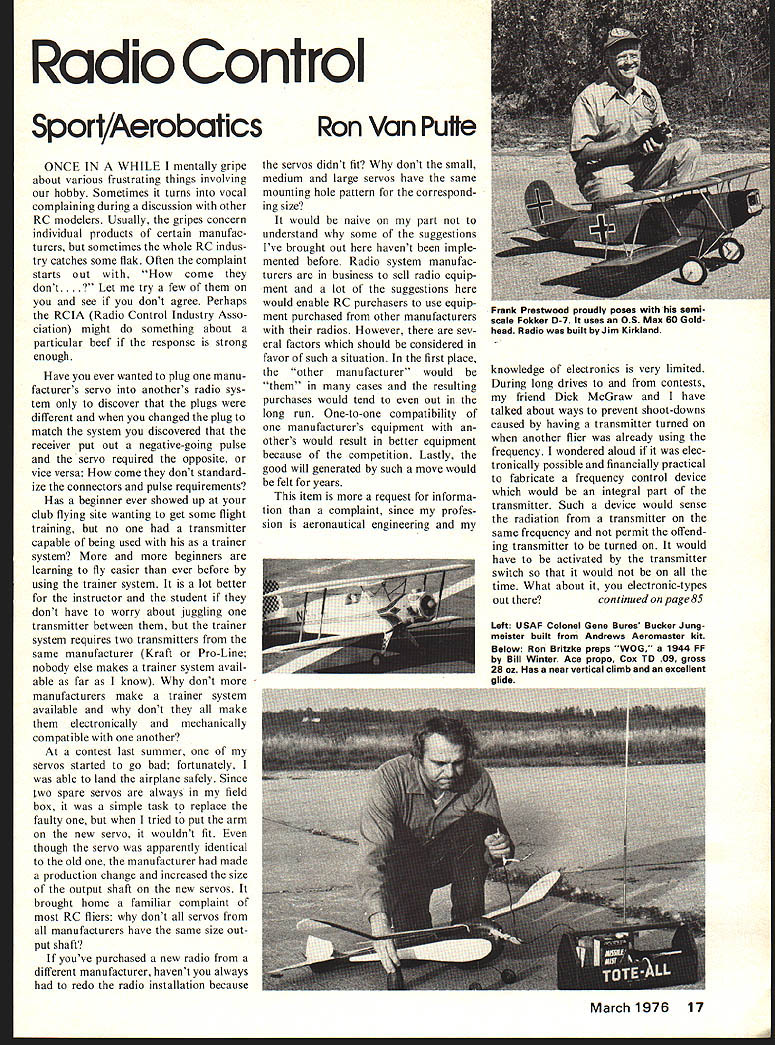
This item is more a request for information than a complaint, since my profession is aeronautical engineering and my knowledge of electronics is very limited.
During long drives to and from contests, my friend Dick McGraw and I have talked about ways to prevent shoot-downs caused by having a transmitter turned on when another flier was already using the frequency. I wondered aloud if it was electronically possible and financially practical to fabricate a frequency control device which would be an integral part of the transmitter. Such a device would sense the radiation from a transmitter on the same frequency and not permit the offending transmitter to be turned on. It would have to be activated by the transmitter switch so that it would not be on all the time. What about it, you electronic-types out there?
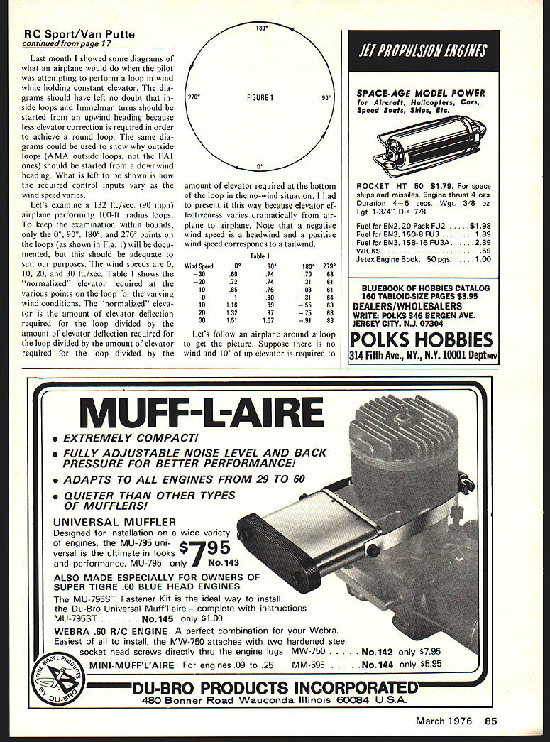
Last month I showed some diagrams of what the airplane would do when the pilot attempted to perform loops with the wind holding constant. Elevator diagrams should have left no doubt that inside loops (Immelmann turns) should be started upwind heading because less elevator correction is required in order to achieve a round loop. The same diagrams could be used to show outside loops. AMA outside loops (fat ones) should be started downwind heading. What was left to be shown was how the required control inputs vary as wind speed varies. Let's examine a 132 ft/sec (90 mph) airplane performing 100-ft radius loops. To keep the examination within bounds, the 0°, 90°, 180° and 270° points of the loops shown in Fig. 1 will be documented; this should be adequate for our purposes. Wind speeds of 0, 10, 20 and 30 ft/sec are used in the table.
RC Sport/Van Putte
amount of elevator required at the bottom of the loop in the no-wind situation. I had to present it this way because elevator effectiveness varies dramatically from airplane to airplane. Note that a negative wind speed is a headwind and a positive wind speed corresponds to a tailwind.
Table 1
Wind Speed 0° 90° 180° 270° -30 .60 .74 .70 .63 -20 .72 .74 .71 .61 -10 .85 .75 .74 .61 0 1.00 1.00 1.00 1.00 10 1.18 .89 .35 .63 20 1.26 .95 -.55 .64 30 1.51 1.07 .91 .83
Let's follow an airplane around a loop to get the picture. Suppose there is no wind and 10° of up elevator is required to get the loop started and through the bottom of the loop. The table entries are the normalized elevator required at the various points on the loop for the varying wind conditions. Multiply the normalized values by the 10° and you have the required elevator at each point. For example, with no wind the bottom requires 10°, at 90° about 10°, at 180° about 10° and at 270° about 10° (all normalized to 1.00).
If there is a headwind (negative wind speed) the required elevator at the top of the loop decreases; with sufficient headwind the elevator at the top becomes zero or even negative (a push). With a tailwind (positive wind speed) the elevator required at the top increases. The numbers in Table 1 illustrate how sensitive the required elevator is to wind speed and direction.
RC Sport (continued)
start the loop. When the airplane is going vertically upward only 8° of up elevator is required. At the top of the loop 3.1° of down elevator is necessary! When the airplane is going vertically downward 6.4° of up elevator is required. At the bottom of the loop the original 10° of up elevator will start the airplane into the second loop.
Compare the previous control inputs with those required to perform the same size loops when there is a 30 ft./sec. headwind. The elevator inputs for the same points on the loop are: 6.0°, 7.4°, 7.0°, 6.3° and 6.0°. The small elevator input changes required make it much easier to do a perfect loop. By comparison, take a look at the control inputs required for a perfect loop in a 30 ft./sec. tailwind; it would take a world champion to be able to coordinate the substantial control input changes which are necessary!
There is an airplane speed, loop size, and wind speed combination which results in minimum required control input variation. We don't really have the option to make the loops too large or too small compared to what the judges are looking for. However, it is worth investigating the characteristics of your airplane because the optimum condition for it may be near to what the judges want and if you can paint three concentric, perfectly circular loops in the sky, the judges may overlook a minor size discrepancy!
Last month I commented that the character of the Class A pattern competition had changed substantially from the original intent. Due to the difficulty of "graduating" into B pattern, the quality of flying proficiency in Class A has improved to the point that a beginner faces the staggering task of competing with an apparently unbeatable group of fliers in this class. The reaction of many clubs to this situation has been to avoid the conflict between truly novice A-pattern fliers and the good (or even great) A-pattern competitors by offering different forms of competition.
The most common variation to the standard contest is to offer Novice, Advanced and Expert categories of Class A. The way of deciding who competes where seems to vary around the country. Each flier competes with other fliers of nearly the same ability and has a chance to win. One thing I don't understand is how advancement points are awarded. Can anyone clarify the situation?
Another contest variation is called the Continental Pattern. This is a brainchild of Canadian Percy Grondin and AMA District IX Vice President Jim Mowery. Each flier makes up his own pattern from a list of maneuvers. Up to 12 maneuvers may be chosen from the list, but the pattern must include take-off, landing, perfect loop and spot landing. Each maneuver has its own K factor (a measure of difficulty) which is multiplied times the score earned for the maneuver. The lowest total score for all flights is subtracted from the highest total score. The difference is divided by the number of categories of competition. The resulting number is added progressively to the lowest score to obtain the point spread for each category. Let's try an example of three categories when the lowest score is 1,000 and the highest is 4,000. The difference is 3,000 and 1/3 of that is 1,000. So, the categories would be 1,000-2,000 points, 2,000-3,000 points, and 3,000-4,000 points.
The Continental Pattern generally allows fliers of nearly the same ability to compete with one another with an equal chance to win a particular category. Unfortunately, each flier has an equal chance to lose since a few extra points may promote a flier from the top of one category to the bottom of another. Nevertheless, it is a refreshing approach to revitalizing pattern competition.
Next month I'll plan to discuss the techniques for determining the proper center of mass of your new creation without calling on the local expert.
(My address is 12 Connie Dr., Shalimar, Fla. 32579.)
Transcribed from original scans by AI. Minor OCR errors may remain.

