
Radio Control Systems the Real Basics
Last month I introduced the subject of learning model aviation “from the ground up.” As the name implies, this is a beginner series devoted to people at the entry point of our wonderful hobby. The sequence of articles planned for this series follows a logical order to allow you to enjoy the learning process. After all, it is a hobby and it is supposed to be fun.
Since approximately 90% of model-flying enthusiasts resort to radio control (RC) systems for flight control, this was judged the best starting place. The article has literally been developed from square one. If you already have some knowledge of RC devices, you might consider this presentation too basic. We will try to describe all aspects of RC for the benefit of the entry-level hobbyist.
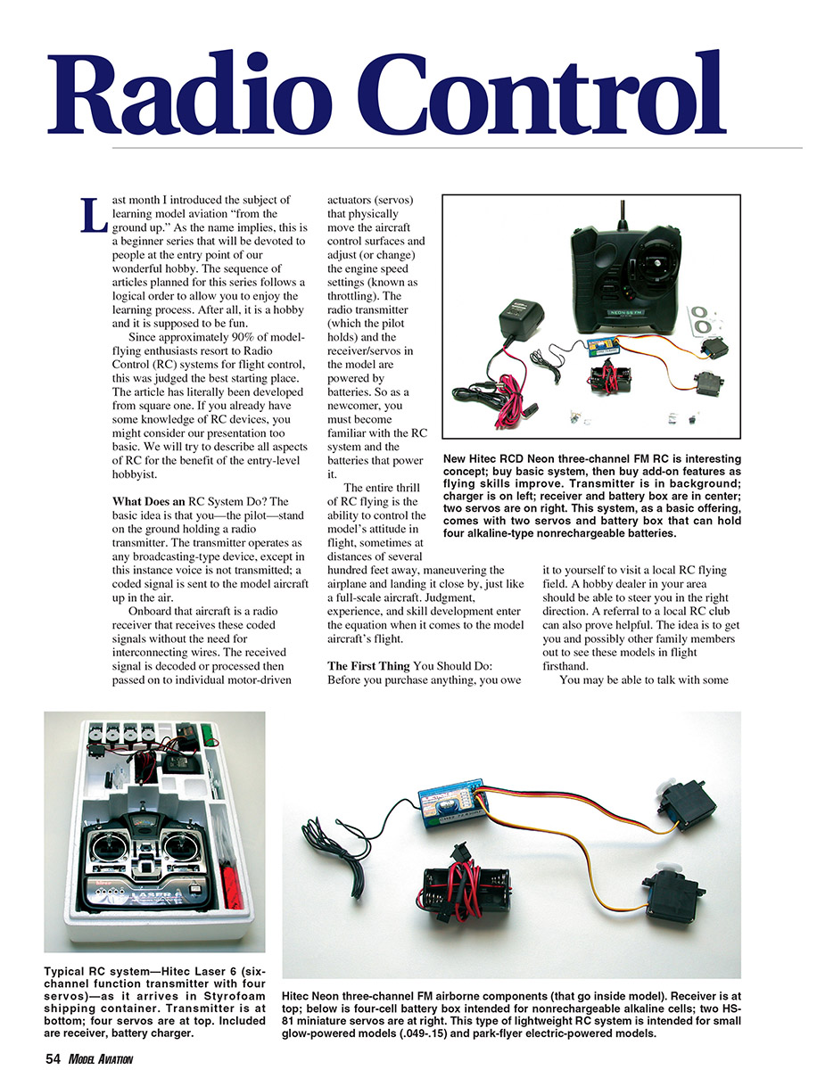
What Does an RC System Do? The basic idea is that you—the pilot—stand on the ground holding a radio transmitter. The transmitter operates as any broadcasting-type device, except in this instance voice is not transmitted; a coded signal is sent to the model aircraft up in the air.
Onboard that aircraft is a radio receiver that receives these coded signals without the need for interconnecting wires. The received signal is decoded or processed, then passed on to individual motor-driven actuators (servos) that physically move the aircraft control surfaces and adjust the engine speed settings (throttle). The radio transmitter (which the pilot holds) and the receiver/servos in the model are powered by batteries. As a newcomer, you must become familiar with the RC system and the batteries that power it.
The entire thrill of RC flying is the ability to control the model’s attitude in flight, sometimes at distances of several hundred feet away, maneuvering the airplane and landing it close by, just like a full-scale aircraft. Judgment, experience, and skill development enter the equation when it comes to the model aircraft’s flight.
The First Thing You Should Do Before you purchase anything, visit a local RC flying field. A hobby dealer in your area should be able to steer you in the right direction. A referral to a local RC club can also prove helpful. The idea is to get you and possibly other family members out to see these models in flight firsthand.
You may be able to talk with some of the experienced fliers and get a rough idea of what is involved. These same people should be able to make initial recommendations concerning types of RC systems, popular system brand names, model aircraft suitable for initial flight instruction, engines to power the airplanes, and the necessary supporting equipment to get you started. All of these elements will be discussed in-depth as this series grows month by month.
How Are RC Systems Classified? RC systems in the most basic sense provide control of the aircraft rudder (for steering left and right), elevator (for pitch control or up and down motion), and engine throttle (control of engine speeds from idle up through full power). Each of these basic flight-control functions is classified as a channel function (rudder, elevator, and throttle). Keeping that in mind, RC systems are classified by the number of channel functions offered—two, three, four, and in the cases of the most advanced systems, upward of eight to ten.
When you shop for your first new RC system, you will see a few basic two-channel systems (rudder and elevator); they are only suitable for flying model gliders or sailplanes, where engines are not employed and a throttle is unnecessary. Since two-channel control is limited in application, the initial point of consideration when buying your first radio is a three-channel RC system.
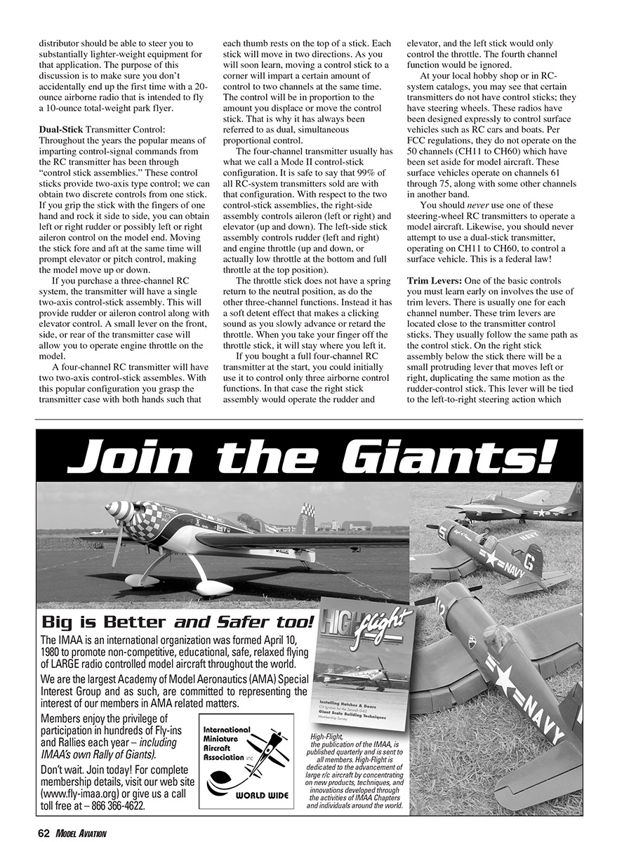
A three-channel RC system provides basic rudder, elevator, and engine control (sometimes called throttle). Several manufacturers, including Futaba and Hitec, make excellent, easy-to-use three-channel RC systems that are also inexpensive. Since so much can be done with a three-channel RC system, it will probably never become obsolete. Many of us who fly sophisticated radio systems still own and regularly use three-channel systems because they are easy to operate.
Looking ahead, there are four-channel RC systems, which comprise the most popular category. With four channels, the added control is ailerons, located on the wing and permitting the model to bank in flight. By adding aileron control to rudder, elevator, and engine control, you have essentially the same form of control as used on full-scale aircraft. As you progress in the RC hobby, you will sooner or later want to expand your horizons and use all four basic channel functions.
Your first choice for an RC system should be a three-channel radio. That will hold your initial investment to a minimum. If you enjoy the hobby and want to grow with it, it would be best if your second radio system were what we call a “full four-channel” system.
RC-System Operating Frequencies After selecting the number of channel functions, your next choice is what frequency to operate on. This discussion is most important because it involves a basic safety requirement you must always observe as an RC pilot.
Years ago the model-aircraft hobby was granted a series of 50 specific frequencies for RC use by the Federal Communications Commission (FCC). Just as the FCC assigns radio and television stations, it has assigned our frequencies which exist in a band that runs from 72.000 megahertz (MHz) to 73.000 MHz. Each of the 50 FCC-approved frequencies (such as 72.010 MHz, 72.030 MHz, etc.) has been assigned a channel number for easy identification purposes.
The term "channel number" has nothing to do with the channel control functions discussed earlier. I mention this because that point has caused initial confusion for many beginners.
Each RC channel (number) is essentially the same as a radio-station number or call sign. If you purchase an RC system on channel 11, it will broadcast a signal on that exact frequency. In this regard, channel number and frequency are one and the same.
When you purchase your radio system, there will probably be a label on the box containing the frequency (expressed in MHz, such as 72.010 MHz) and its equivalent channel number (in this case CH11). When you open the box, the RC transmitter and receiver will probably be stamped with the operating frequency and the channel number.
RC receivers on the same frequency/channel can receive the same signal. This is important. If you own an RC system that operates on CH11 and another modeler shows up at the flying field with the same channel number, you can't operate or fly at the same time. Attempting to do so will lead to possible radio interference and could result in one or both models crashing. This is your first safety lesson as an RC pilot.
If two modelers show up at the field using the same channel, each must wait his or her turn so that only one model is operated at a time. To simplify the control of these channel numbers, a two-digit-numbered flag is supplied with every RC system. That flag must always be prominently displayed on the transmitter antenna for all to see.
Each RC flying field usually has a display board that contains a group of numbered clothespins or clips. There will be 50 of these pins or clips running from CH11 to CH60. The drill is simple: when you want to turn on your RC transmitter at the field, you must first go to this channel-control board. If the clip for your channel is on the board, that means it is not in use. Remove that clip and attach it to the transmitter antenna. At this point you may turn on the power to that transmitter for test or flying purposes.
While you are "on the air," if any other modeler intends to operate on the same channel number and goes to the board, the missing clip will alert him or her that that channel is in use. That person must wait until you are finished flying, have turned off your transmitter, and have returned the channel clip to the control board. It's a simple drill, but if followed faithfully it will prevent any chance of interference or model crashes. There are more detailed subtleties to these procedures, but they will be left for later.
FM, PCM, and AM Modes of Transmission
Since we are dealing with "radio," you should be familiar with the terms AM (Amplitude Modulation) and FM (Frequency Modulation) from broadcast radio. Except for the station numbers or call signs, you can usually receive both broadcast modes on the same radio, and for the most part they sound the same.
In the RC hobby we can use AM, FM, and a special form of FM called PCM (Pulse Code Modulation). The most popular operating mode today is FM—much like in broadcasting. The majority of RC systems sold are FM; it has been that way for the last 20 years. FM provides good, reliable control and can be purchased at reasonable prices. Few RC systems are still offered on AM.
Some sophisticated RC systems are offered on a PCM mode. It adds a proprietary digital code on top of the FM signal, offering more protection from outside interference. PCM-type modulation is only found on the more advanced and more costly systems.
As a beginner, the one important thing you must keep in mind is that you can't mix modulation types between a transmitter and receiver; that is, an AM transmitter will not operate an FM receiver, an FM transmitter will not operate a PCM receiver, etc. The modulation types must match.
Remainder of RC System Components
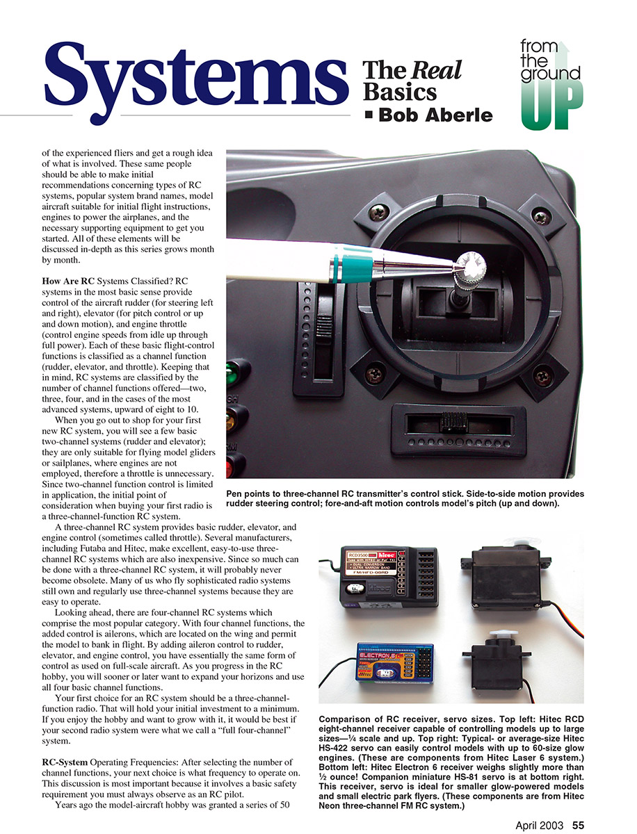
So far we have discussed only the RC transmitter. When you purchase a full RC system, included in the box will be the "airborne components" (the equipment that must go in your model) and supporting equipment necessary to make the system operate.
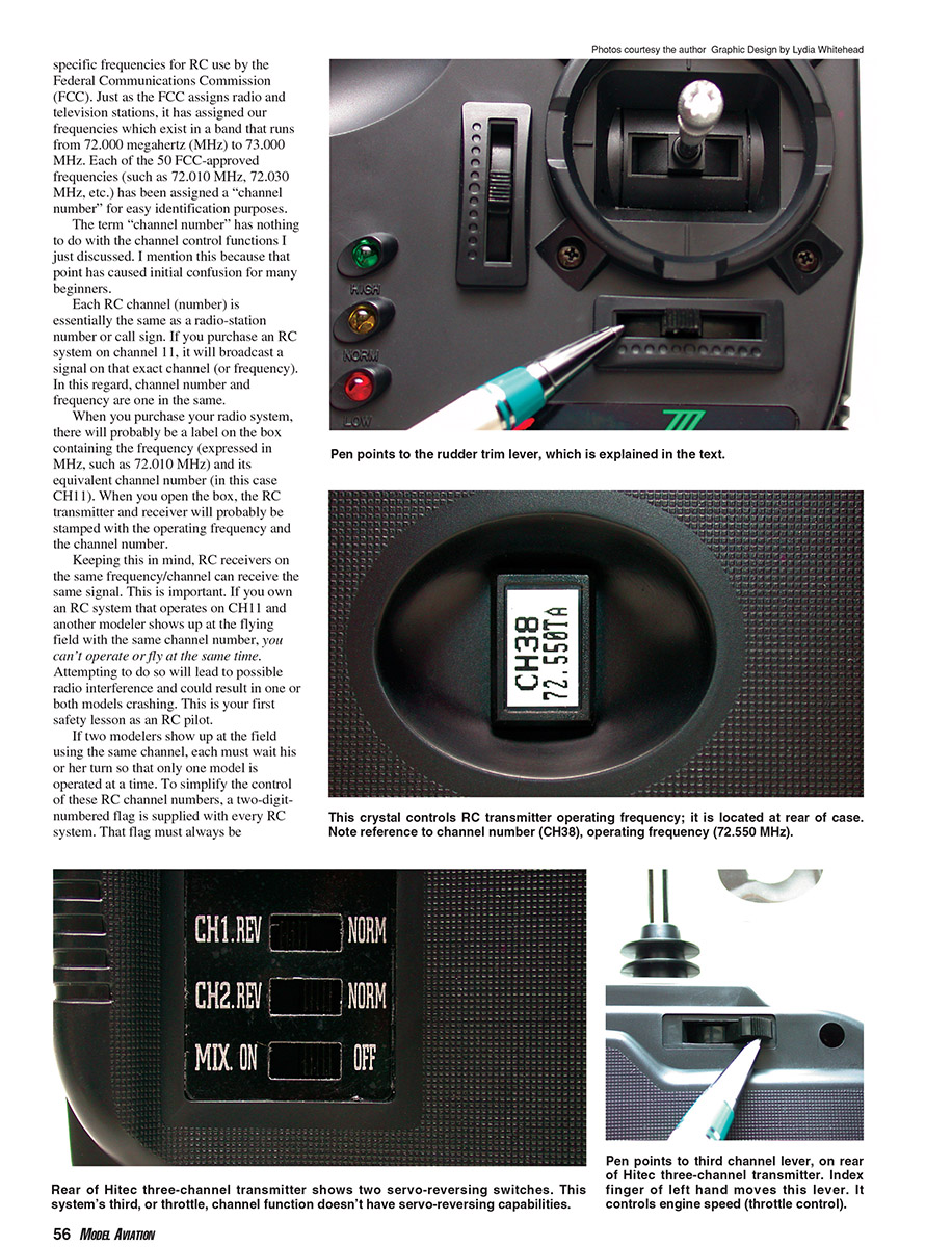
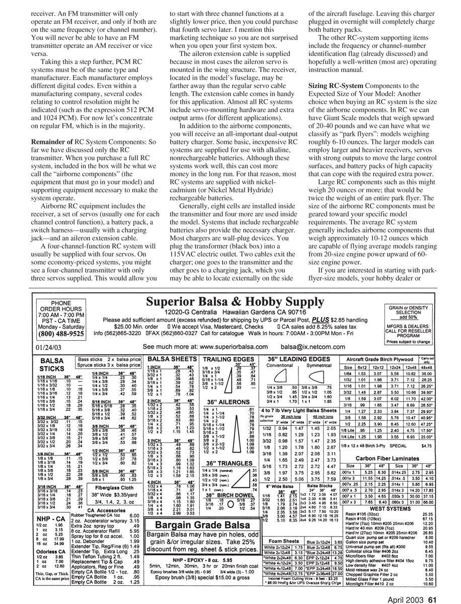
Airborne RC equipment includes the receiver, a set of servos (usually one for each channel control function), a battery pack, a switch harness—usually with a charging jack—and an aileron extension cable.
A four-channel RC system will usually be supplied with four servos. On some economy-priced systems, you might see a four-channel transmitter with only three servos supplied. This would allow you to start with three channel functions at a slightly lower price and purchase the fourth servo later. I mention this marketing technique so you are not surprised when you open your first system box.
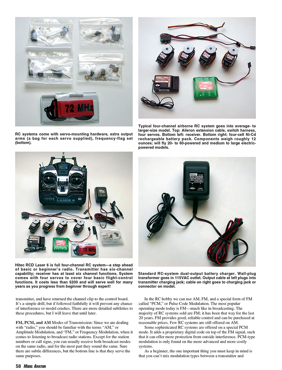
The aileron extension cable is supplied because in most cases the aileron servo is mounted in the wing structure. The receiver, located in the model's fuselage, may be farther away than the regular servo cable length. The extension cable comes in handy for this application. Almost all RC systems include servo-mounting hardware and extra output arms for different applications.
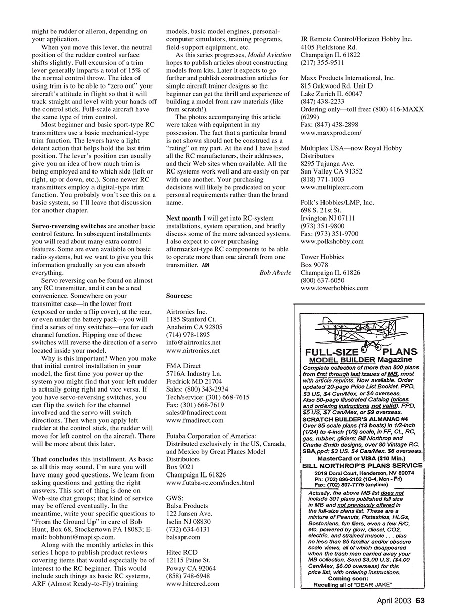
In addition to the airborne components, you will receive an all-important dual-output battery charger. Some basic, inexpensive RC systems are supplied for use with alkaline, nonrechargeable batteries. Although these systems work well, this can cost more money in the long run. For that reason, most RC systems are supplied with nickel-cadmium (NiCd) or nickel-metal-hydride (NiMH) rechargeable batteries.
Generally, eight cells are installed inside the transmitter and four more are used inside the model. Systems that include rechargeable batteries also provide the necessary charger. Most chargers are wall-plug devices. You plug the transformer (black box) into a 115 VAC electric outlet. Two cables exit the charger: one goes to the transmitter and the other goes to a charging jack, which you may be able to locate externally on the side of the aircraft fuselage. Leaving this charger plugged in overnight will completely charge both battery packs.
Other supporting items include the frequency or channel-number identification flag (already discussed) and a well-written operating instruction manual.
Sizing RC-System Components to the Expected Size of Your Model
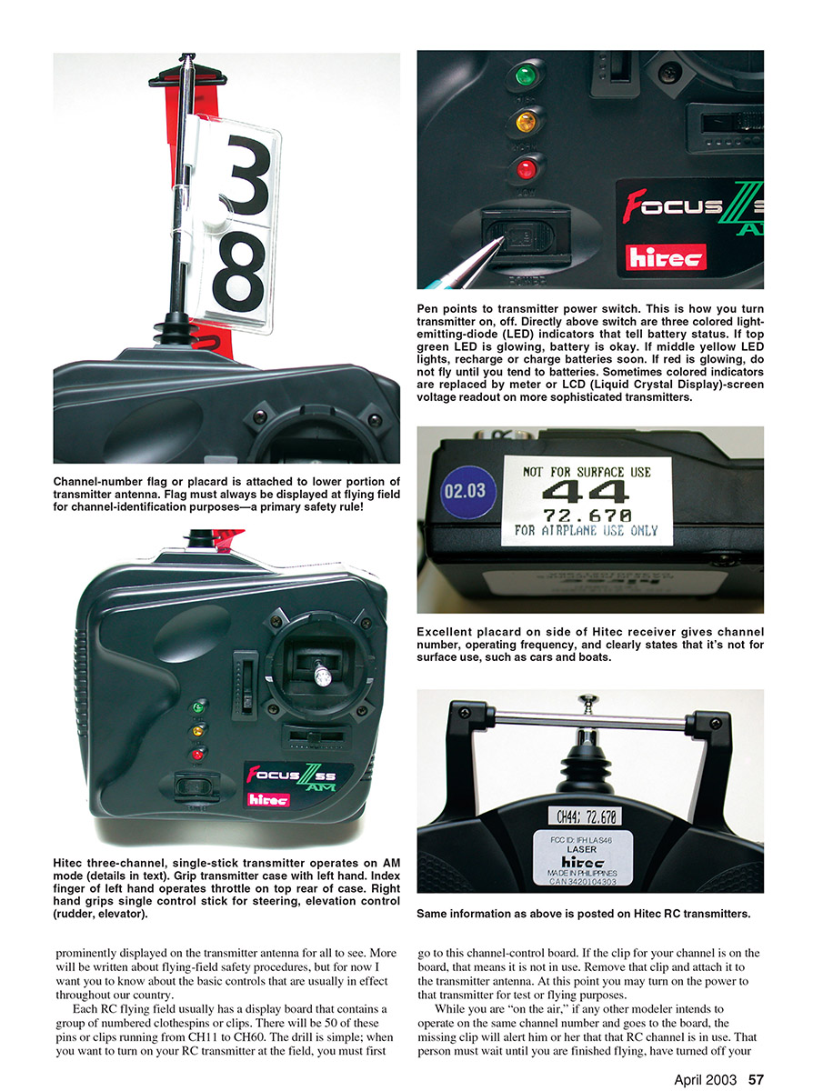
Another choice when buying an RC system is the size of the airborne components. In RC we can have giant-scale models that weigh upward of 20–40 pounds and we can have what we classify as "park flyers": models weighing roughly 6–10 ounces. The larger models can employ larger and heavier receivers, servos with strong outputs to move the large control surfaces, and battery packs of high capacity to cope with the required extra power.
Large RC components such as this might weigh 20 ounces or more; that would be twice the weight of an entire park flyer. The size of the airborne RC components must be geared toward your specific model requirements. The average RC system generally includes airborne components that weigh approximately 10–12 ounces and are capable of flying average models ranging from 20-size engine power up to 60-size engine power.
If you are interested in starting with park-flyer-size models, your hobby dealer or distributor should be able to steer you to substantially lighter-weight equipment for that application. The purpose of this discussion is to make sure you don't accidentally end up the first time with a 20-ounce airborne radio that is intended to fly a 10-ounce total-weight park flyer.
Dual-Stick Transmitter Control
Throughout the years the popular means of imparting control-signal commands from the RC transmitter has been through control-stick assemblies. These control sticks provide two-axis type control; we can obtain two discrete controls from one stick. If you grip the stick with the fingers of one hand and rock it side to side, you can obtain left or right rudder or left or right aileron control on the model end. Moving the stick fore and aft at the same time will prompt elevator or pitch control, making the model move up or down.
If you purchase a three-channel RC system, the transmitter will have a single two-axis control-stick assembly. This will provide rudder or aileron control along with elevator control. A small lever on the front, side, or rear of the transmitter case will allow you to operate engine throttle on the model.
A four-channel RC transmitter will have two two-axis control-stick assemblies. With this popular configuration you grasp the transmitter case with both hands such that each thumb rests on the top of a stick. Each stick will move in two directions. Moving a control stick to a corner will impart control to two channels at the same time. The control will be in proportion to the amount you displace or move the control stick; that is why it has always been referred to as dual, simultaneous proportional control.
The four-channel transmitter usually has what we call a Mode II control-stick configuration. It is safe to say that 99% of all RC-system transmitters sold use that configuration. For the two control-stick assemblies, the right-side stick controls aileron (left or right) and elevator (up and down). The left-side stick controls rudder (left and right) and engine throttle (up and down, with low throttle at the bottom and full throttle at the top position).
The throttle stick does not have a spring return to the neutral position, as do the other three channel functions. Instead it has a soft detent effect that makes a clicking sound as you slowly advance or retard the throttle. When you take your finger off the throttle stick, it will stay where you left it.
If you bought a full four-channel RC transmitter at the start, you could initially use it to control only three airborne control functions. In that case the right stick assembly would operate the rudder and elevator, and the left stick would only control the throttle. The fourth channel function would be ignored.
At your local hobby shop or in RC-system catalogs, you may see that certain transmitters do not have control sticks; they have steering wheels. These radios are designed expressly to control surface vehicles such as RC cars and boats. Per FCC regulations, they do not operate on the 50 channels (CH11 to CH60) which have been set aside for model aircraft. Surface-vehicle radios operate on channels 61 through 75, along with some other channels in another band.
You should never use one of these steering-wheel RC transmitters to operate a model aircraft. Likewise, you should never attempt to use a dual-stick transmitter, operating on CH11 to CH60, to control a surface vehicle. This is a federal law.
Trim Levers
One of the basic controls you must learn early on involves the use of trim levers. There is usually one for each channel. These trim levers are located close to the transmitter control sticks. They usually follow the same path as the control stick. On the right stick assembly, below the stick, there will be a small protruding lever that moves left or right, duplicating the same motion as the rudder-control stick. This lever will be tied to the left-to-right steering action, which controls rudder or aileron depending on your application.
When you move this lever, the neutral position of the control surface shifts slightly. Full excursion of a trim lever generally imparts a total of about 15% of the normal control throw. The idea of using trim is to be able to "zero out" your aircraft's attitude in flight so that it will track straight and level with your hands off the control stick. Full-scale aircraft have the same type of trim control.
Most beginner and basic sport-type RC transmitters use a basic mechanical-type trim function. The levers have a light detent action that helps hold the last trim position. The lever's position can usually give you an idea of how much trim is being employed and to which side (left or right, up or down, etc.). Some newer RC transmitters employ a digital-type trim function. You probably won't see this on a basic system, so that discussion is left for another chapter.
Servo-reversing switches are another basic control feature. In subsequent installments you will read about many extra control features. Some are even available on basic radio systems, but we want to give you this information gradually so you can absorb everything.
Servo reversing can be found on almost any RC transmitter, and it can be a real convenience. Somewhere on your transmitter case—in the lower front (exposed or under a flip cover), at the rear, or even under the battery pack—you will find a series of tiny switches—one for each channel function. Flipping one of these switches will reverse the direction of a servo located inside your model.
Why is this important? When you make that initial control installation in your model, the first time you power up the system you might find that your left rudder is actually going right and vice versa. If you have servo-reversing switches, you can flip the switch for the channel involved and the servo will switch directions. Then when you apply left rudder at the control stick, the rudder will move left on the aircraft. There will be more about this later.
That concludes this installment. As basic as all this may sound, I'm sure you will have many good questions. We learn from asking questions and getting the right answers. This sort of thing is done on Web-site chat groups; that kind of service may be offered eventually. In the meantime, write your specific questions to "From the Ground Up" in care of Bob Aberle, Box 68, Stockton PA 18083; E-mail: bobhunt@mapisp.com.
Along with the monthly articles in this series I hope to publish product reviews covering items that would especially be of interest to the RC beginner. This would include such things as basic RC systems, ARF (Almost Ready-to-Fly) training models, basic model engines, personal-computer simulators, training programs, field-support equipment, etc.
As this series progresses, Model Aviation hopes to publish articles about constructing models from kits. Later it expects to go further and publish construction articles for simple aircraft trainer designs so the beginner can get the thrill and experience of building a model from raw materials.
The photos accompanying this article were taken with equipment in my possession. The fact that a particular brand is not shown should not be construed as a "rating" on my part. At the end I have listed RC manufacturers, their addresses, and their web sites when available. All the RC systems work well and are easily on par with one another. Your purchasing decisions will likely be predicated on your personal requirements rather than the brand name.
Next month I will get into RC-system installations, system operation, and briefly discuss some of the more advanced systems. I also expect to cover purchasing aftermarket-type RC components to be able to operate more than one aircraft from one transmitter.
Bob Aberle
Sources
- Airtronics Inc., 1185 Stanford Ct., Anaheim, CA 92805; (714) 978-1895; info@airtronics.net; www.airtronics.net
- FMA Direct, 5716A Industry Ln., Frederick, MD 21704; Sales: (800) 343-2934; Tech/service: (301) 668-7615; Fax: (301) 668-7619; sales@fmadirect.com; www.fmadirect.com
- Futaba Corporation of America, distributed in the US, Canada, and Mexico by Great Planes Model Distributors, Box 9021, Champaign, IL 61826; www.futaba-rc.com/index.html
- GWS Balsa Products, 122 Jansen Ave., Iselin, NJ 08830; (732) 634-6131; balsapr.com
- Hitec RCD, 2115 Paine St., Poway, CA 92064; (858) 748-6948; www.hitecrcd.com
- JR Remote Control / Horizon Hobby Inc., 4105 Fieldstone Rd., Champaign, IL 61822; (217) 355-9511
- Maxx Products International, Inc., 815 Oakwood Rd., Unit D, Lake Zurich, IL 60047; (847) 438-2233; Ordering only—toll free: (800) 416-MAXX (6299); Fax: (847) 438-2898; www.maxxprod.com
- Multiplex USA (now Royal Hobby Distributors), 8295 Tujunga Ave., Sun Valley, CA 91352; (818) 771-1003; www.multiplexrc.com
- Polk's Hobbies / LMP, Inc., 698 S. 21st St., Irvington, NJ 07111; (973) 351-9800; Fax: (973) 351-9700; www.polkshobby.com
- Tower Hobbies, Box 9078, Champaign, IL 61826; (800) 637-6050; www.towerhobbies.com
Transcribed from original scans by AI. Minor OCR errors may remain.

