
Radio Technique
George M. Myers
Batteries and Diodes
WHILE HELPING a friend pick up the pieces I was moved to ask him why, in this day of 3-wire servos and low-voltage receivers, he would operate a radio system without diode protection of the battery pack. The answer was simple and direct: "Because I don't know what size to use, or how to install them!" Before beginning a step-by-step instruction, a little background information may be in order.
The nicad battery is a single-point failure item in your system. If the battery fails, the system stops operating. Batteries fail in two modes: Open (no current flows through) and Short (no voltage is generated, but current does flow through the battery, if driven by other operating batteries). Short circuits are more common, and they are frequently caused by letting a battery lie unattended over the winter season, so that it spends a considerable time at 0 volts state of discharge. A short-circuited cell in your battery pack will cause the system to show decreased range and if the shorted cell is in the airborne pack, the servos will run slower. An open cell acts just like a switch, and it turns the system "off."
A diode is a device that conducts current freely in one direction and, ideally, not at all in the opposite direction. This makes it ideal for our purposes, because we can connect it across a battery so that it will conduct in the same direction as the battery, without fear of discharging the cell accidentally. (See Fig. 1.) Now, if we shunt each cell in our battery pack with a diode, any cell can develop an open circuit without turning the system "off". There is a price for this service, which is the voltage drop caused by the diode when it is conducting. For a fully-charged airborne pack, the output voltage will drop from about 5.6 to 4.2 VDC when one cell develops a short. It will drop to zero if the cell develops an open circuit, of course. Connecting a diode across the open cell will restore the circuit with an output of about 3.4 volts. The missing voltage was absorbed by the diode. In the worst case, a pack at 4.4 volts will drop to 2.5 volts. Now, most modern receivers will operate at voltages around 3.0 reliably and 3-wire servos will still function (slowly and weakly) at that voltage. This will allow you at least one chance at making a good landing after things go sour on you.
Pro-Line Electronics, 10632 North 21st Ave., Suite 11, Phoenix, AZ 85029, was the first to use diode-protected battery packs commercially, as far as I know, and they still offer them. Readers who desire diode protection and are unsure of their ability to install their own are strongly advised to buy such packs. I do not want to be blamed for problems arising from incorrect installations. Connecting a diode backwards will discharge your battery. You should notice the problem right away, because the diode will get hot. Still, buy some silicon diodes rated at least 1 amp and 50 volts, such as the 1N4001.
Next, test each diode in the setup of Fig. 2. Test each diode both ways. The voltmeter should read about 5.2 volts when no diode is connected. It should read the same when a diode is connected + to +. If not, discard the diode. The + end of the diode is marked with a band around the body of the diode. When a diode is connected + to -, the indicated voltage should be less than 0.8 volts. If a higher voltage is seen, set that diode aside for some other use.
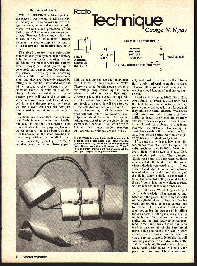
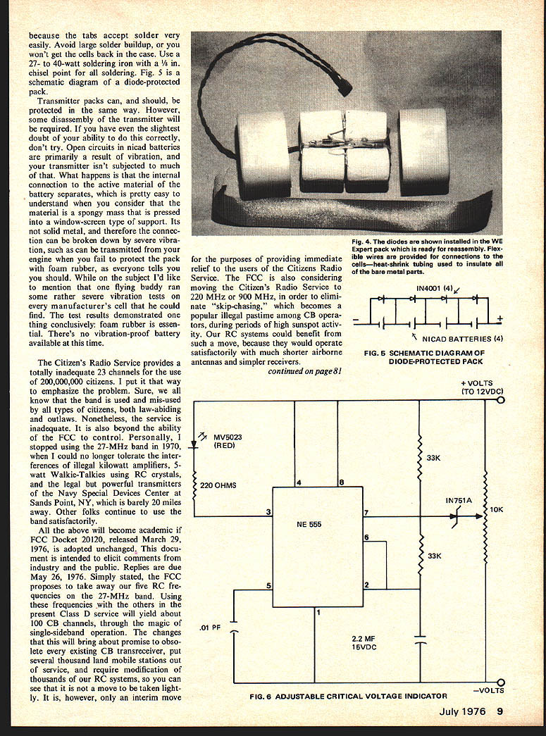
Fig. 3 shows a World Engines Expert pack, with a diode string assembled and fitted into the groove formed by the walls of the cylindrical cells. Note that flexible wires are provided to make connections to the cells. This is done to allow some free motion for the purpose of installing the cells back into the pack. A rigid setup might break. Fig. 4 shows the diodes installed and the pack ready to be reassembled. Note that shrink tubing has been used to insulate all of the bare metal parts. Failure to do this can lead to short circuits that are worse than the condition you are trying to avoid. Note also that all soldering is done to the tabs on the cells, and that only 60/40 rosin-core solder is used. Acid solder fluxes will ruin your pack, and are completely unnecessary.
Transmitter packs can and should be protected the same way. However, some disassembly of the transmitter will be required. If you have the slightest doubt of your ability, don't try. Open circuits in nicad batteries primarily result from vibration; the transmitter isn't subjected much. What happens is the internal connection of the active material to the cell's support separates. It's pretty easy to understand; consider the material a spongy mass pressed into a window-screen type support. Its solid metal therefore connection can be broken down by severe vibra tion , such as can be transmitted from your engine when you fail to protect the pack with foam rubber, as everyone tells you should. While on the subject I'd like to mention that one flying buddy ran some rather severe vibration tests on every manufacturer's cell that he could find. The test results demonstrated one thing conclusively; foam rubber is essential. There's no vibration-proof battery available at this time.
The Citizen's Radio Service provides a totally inadequate 23 channels for the use of 200,000,000 citizens. I put it that way to emphasize the problem. Sure, we all know that the band is used and mis-used by all types of citizens, both law-abiding and outlaws. Nonetheless, the service is inadequate. It is also beyond the ability of the FCC to control. Personally, I stopped using the 27-MHz band in 1970, when I could no longer tolerate the interferences of illegal kilowatt amplifiers, 5-watt Walkie-Talkies using RC crystals, and the legal but powerful transmitters of the Navy Special Devices Center at Sands Point, NY, which is barely 20 miles away. Other folks continue to use the band satisfactorily.
All the above will become academic if FCC Docket 20120, released March 29, 1976, is adopted unchanged. This document is intended to elicit comments from industry and the public. Replies are due May 26, 1976. Simply stated, the FCC proposes to take away our five RC frequencies on the 27-MHz band. Using these frequencies with the others in the present Class D service will yield about 100 CB channels, through the magic of single-sideband operation. The changes that this will bring about promise to obsolete every existing CB transceiver, put several thousand land mobile stations out of service, and require modification of thousands of our RC systems, so you can see that it is not a move to be taken lightly. It is, however, only an interim move for the purposes of providing immediate relief to the users of the Citizens Radio Service. The FCC is also considering moving the Citizen's Radio Service to 220 MHz or 900 MHz, in order to eliminate "skip-chasing," which becomes a popular illegal pastime among CB operators during periods of high sunspot activity. Our RC systems could benefit from such a move, because they would operate satisfactorily with much shorter airborne antennas and simpler receivers.
Radio Technique/Myers
The proposed Section 95.47 (b) authorizes continued use of RC on 27 MHz, but on frequencies shared with radiotelephony. It may work in some remote areas, but that's all. Legalizing shared usage is the same thing as eliminating it, because only the RC flier will be hurt by it. I don't see much point in protesting this one, but what I think we should do is seek compensation in the form of assignment of exclusive RC channels elsewhere in the frequency spectrum. There are several public service channels in the 32- to 42-MHz band which are almost abandoned. They could be made available to us. Conversion of existing systems probably wouldn't cost more than $50 for a transmitter and receiver. Docket 20119, released February 12, 1976, holds out hope for 100-mw unlicensed operation on five frequencies in the 49.82-49.90 MHz band. 100 mw at these frequencies will be similar in performance to 200 mw on 27 MHz, about what we had five years ago. In addition, Docket 20282 offers the opportunity for "Application only" licensing for use of the 54-MHz (6 meter) Amateur Radio band. Most 27-MHz sets are easily convertible for this band.
Section 95.51(h) 10 (3) requires that all frequency-determining circuitry (including crystals) employed in Class D equipment be internal to the equipment and not accessible from the exterior of the cabinet. As I read it, this makes the Heath and Kraft 1976 transmitters illegal. I understand that the word "internal" was not intended to have that effect, but taken with the combining of classes C and D, that's what they say. I think we should protest this one, and seek an exception. I'm sure the manufacturers will do that.
I'm told that AMA would prefer that all responses to Docket 20120 be addressed directly to the FCC as per the instructions in the AMA News section of this magazine. The closing date as I write this is May 26, 1976. An extension is possible, but don't depend on it.
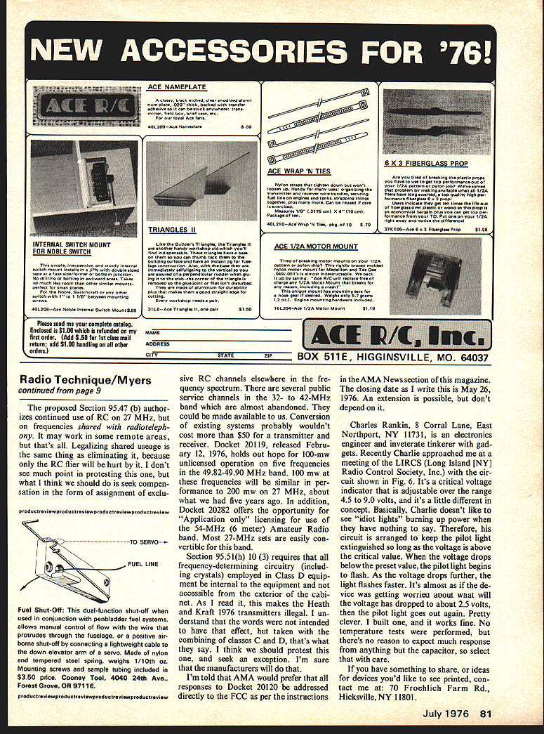
Charles Rans, 8 Corral Lane, East Northport, NY 11731, is an electronics engineer and inveterate tinkerer with gadgets. Recently Charlie approached me at a meeting of the LIRCS (Long Island RC) Radio Control Society, Inc. with the circuit shown in Fig. 6. It's a critical voltage indicator that is adjustable over the range 4.5 to 9.0 volts, and it's a little different in concept. Basically, Charlie doesn't like to see "widow lights" burning up power when they have nothing to say. Therefore, his circuit is arranged to keep the pilot light extinguished so long as the voltage is above the critical value. When the voltage drops below the preset value, the pilot light begins to flash. As the voltage drops further, the light flashes faster. It's almost as if the device was getting worried about what will happen as the voltage drops toward about 2.5 volts, then the pilot light goes out again. Pretty clever. I built one, and it works fine. No temperature tests were performed, but there's no reason to expect much response from anything but the capacitor, so select the capacitor with a temperature coefficient you can live with.
If you have something to share, or ideas for devices you'd like to see printed, contact me at: 70 Froehlich Farm Rd., Hicksville, NY 11801.
Transcribed from original scans by AI. Minor OCR errors may remain.

