
Radio Technique
George M. Myers
Sound-Level Meters: Since I have been soliciting suggestions for column subjects I have received several requests for a simple circuit for a sound-level meter. Most often, the thing which prompts the request is a concern for engine noise. The following extract from one of the letters is typical: "... Like most clubs today, ours (the South Jersey Flyaways) is involved in noise problems. By the use of an infrequently available dB meter we have been able to assemble some information on various engine/muffler combinations. At this point we have not reached any concrete position on what is allowable at the club flying site. I assume that our muffler committee will come out in the near future with a recommendation on allowable noise levels. The rub is in the availability of the dB meter... Would you have knowledge of any available circuit diagram which we could use to construct a noise-measuring device of our own?..." — Charles Kline, 7 Meadowlark Rd., Stratford, N. J.
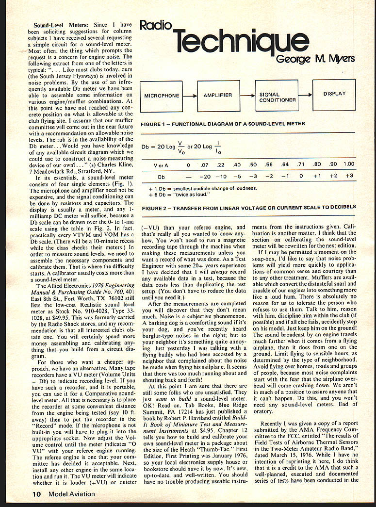
In its essentials, a sound-level meter consists of four single elements (Fig. 1). The microphone and amplifier need not be expensive, and the signal conditioning can be done by resistors and capacitors. The display is usually a meter, and any 1-milliamp DC meter will suffice, because a dB scale can be drawn over the 0- to 1-mA scale using the table in Fig. 2. In fact, practically every VTVM and VOM has a dB scale. (There will be a 10-minute recess while the class checks their meters.) In order to measure sound levels, we need to assemble the necessary components and calibrate them. That is where the difficulty starts. A calibrator usually costs more than a sound-level meter.
The Allied Electronics 1976 Engineering Manual & Purchasing Guide No. 760, 401 East 8th St., Fort Worth, TX 76102 still lists the low-cost Realistic sound level meter as Stock No. 910-4028, Type 331028, at $49.95. This was formerly carried by the Radio Shack stores, and my recommendation is that all interested clubs obtain one. You will certainly spend more money assembling and calibrating anything that you build from a circuit diagram.
For those who want a cheaper approach, we have an alternative. Many tape recorders have a VU meter (Volume Units = dB) to indicate recording level. If you have such a recorder, and it is portable, you can use it for a Comparative sound-level meter. All that is necessary is to place the recorder at some convenient distance from the engine being tested (say 10 ft. away) then to put the recorder in the "Record" mode. If the microphone is not built-in you will have to plug it into the appropriate socket. Now adjust the Volume control until the meter indicates "0 VU" with your referee engine running. The referee engine is one that your committee has decided is acceptable. Next, install any other engine in the same location and run it. The VU meter will indicate whether it is louder (+VU) or quieter (−VU) than your referee engine, and that's really all you wanted to know anyhow. You won't need to run a magnetic recording tape through the machine when making these measurements unless you want a record of what was done. As Test Engineer with some 20+ years experience I have decided that I will always record any available data in a test, because the data costs less than duplicating the test setup. (You don't have to reduce the data until you need it.)
After the measurements are completed you will discover that they don't mean much. Noise is a subjective phenomenon. A barking dog is a comforting sound if it's your dog, and you've recently heard burglar-type noises in the night; but your neighbor's is something quite annoying. Just yesterday I was talking with a flying buddy who had been accosted by a neighbor that complained about the noise he made when flying his sailplane. It seems that there was too much running about and shouting back and forth.
At this point I am sure that there are still some folks who are unsatisfied. They just want to build a sound-level meter. OK! Read on. Tab Books, Blue Ridge Summit, PA 17214 has just published a book by Robert P. Haviland entitled Build Your Own Miniature Test and Measurement Instruments, $4.95. Chapter 12 tells how to build and calibrate your own sound-level meter in a package about the size of the Heath "Thumb-Tac." First Edition, First Printing was January 1976, so your local electronics supply house or bookstore should have it by now. It's new, up-to-date, and well-written. You should have no trouble producing useable instruments from the instructions given. Calibration is another matter. I think that the section on calibrating the sound-level meter will be rewritten for the next edition.
If I may be permitted a moment on the soap-box, I'd like to say that noise problems will yield more quickly to applications of common sense and courtesy than to any other treatment. Mufflers are available which convert the distasteful snarl and crackle of our engines into something more like a loud hum. There is absolutely no reason for us to tolerate the person who refuses to use them. Talk to him, reason with him, discipline him within the club (if possible) and if all else fails, accidentally step on his model. Just keep him on the ground! The sound broadcast by an engine travels much further when it comes from a flying airplane than it does from one on the ground. Limit flying to sensible hours, as determined by the type of neighborhood. Avoid flying over homes, roads and groups of people, because most noise complaints start with the fear that the airplane overhead will come crashing down. We aren't in much of a position to assure anyone that it can't happen. Do this, and you won't need any sound-level meters. End of oratory.
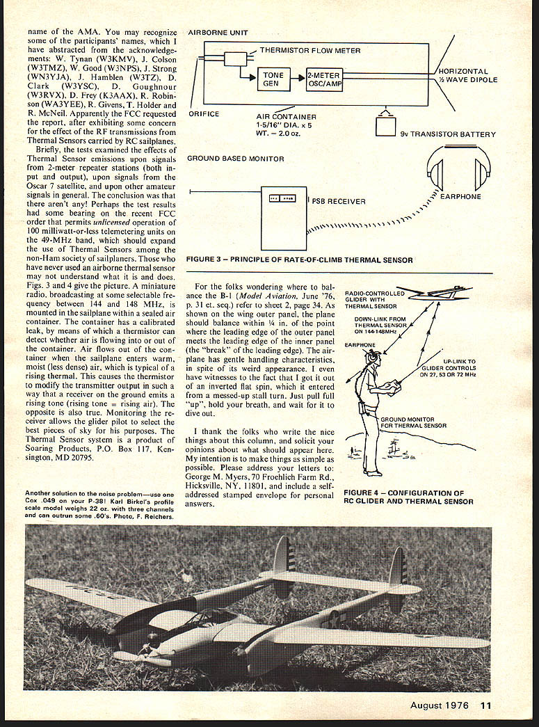
Recently I was given a copy of a report submitted by the AMA Frequency Committee to the FCC, entitled "The Results of Field Tests of Airborne Thermal Sensors in the Two-Meter Amateur Radio Band," dated March 15, 1976. While I have no intention of reprinting it here, I do think that it is a credit to the AMA that such a well-planned, executed and documented series of tests have been conducted in the
FIGURE 1 — FUNCTIONAL DIAGRAM OF A SOUND-LEVEL METER
MICROPHONE → AMPLIFIER → SIGNAL CONDITIONER → DISPLAY
dB = 20 Log V/V0 or 20 Log I/I0
V or A: 0 .07 .22 .40 .50 .56 .64 .71 .80 .90 1.00 dB: −20 −10 −5 −3 −2 −1 0 +1 +2 +3
+1 dB = smallest audible change of loudness. +6 dB = "twice as loud."
FIGURE 2 — TRANSFER FROM LINEAR VOLTAGE OR CURRENT SCALE TO DECIBELS
Sound-Level Meters
Since we have had a soliciting-suggestions column, the subject has received several requests for a simple circuit sound-level meter. Most often the thing that prompts such requests concerns engine noise. Following is an extract of letters typical of the clubs today. "South Jersey Flyaways involved noise problems; we infrequently have a dB meter available, but have been able to assemble some information on various engine/muffler combinations. At this point we have not reached a concrete position on what is allowable at a club flying site. I assume the muffler committee will come out with a recommendation on allowable noise levels in the near future. Availability of a dB meter would help. Would you have knowledge of a circuit diagram we could use to construct a noise-measuring device of our own?" — Charles Kline, 7 Meadowlark Rd., Stratford, N.J.
Its essentials: a sound-level meter consists of four simple elements (Fig. 1) — microphone, amplifier, signal conditioner and display. You need not expensive signal conditioning; it can be done with resistors and capacitors. The display is usually a 1 milliamp DC meter; this will suffice because a dB scale can be drawn over the 0–1 mA scale using the table (Fig. 2). In fact, practically any VTVM or VOM has a dB scale.
If you will have 10-minute recess class checks or meters in order to measure sound levels, you need to assemble the necessary components and calibrate. The difficulty starts with the calibrator, which usually costs as much as a sound-level meter. Allied Electronics' 1976 Engineering Manual & Purchasing Guide (No. 760), 401 East 8th St., Fort Worth, TX 76102, still lists a low-cost Realistic sound-level meter, Stock No. 910-4028 Type 331028, $49.95, formerly carried by Radio Shack stores. My recommendation to interested clubs is to obtain one; you will certainly spend less money than assembling and calibrating one yourself. If you want a cheaper approach and don't want to build the circuit diagram, an alternative is to use tape recorders that have a VU meter (Volume Units — dB indicate recording level). If you have such a recorder and it is portable, you can use it as a comparative sound-level meter. It is necessary to place the recorder some convenient distance from the engine being tested — say 10 ft away — and put the recorder in the Record mode (the built-in microphone will have a plug or an appropriate socket). Now adjust the Volume control until the meter indicates 0 VU with the reference engine running that the referee or engine committee has decided is acceptable. Next install the other engine in the same location and run. The VU meter will indicate whether it is louder or quieter.
George Myers
FIGURE 3 — PRINCIPLE OF RATE-OF-CLIMB THERMAL SENSOR
For the folks wondering where to balance the B-1 (Model Aviation, June '76, p. 31 et seq.), refer to sheet 2, page 34. As shown on the wing outer panel, the plane should balance within 1/4 in. of the point where the leading edge of the outer panel meets the leading edge of the inner panel (the "break" of the leading edge). The airplane has gentle handling characteristics, in spite of its weird appearance. I even have witnesses to the fact that I got it out of an inverted flat spin, which it entered from a messed-up stall turn. Just pull full "up," hold your breath, and wait for it to dive out.
I thank the folks who write the nice things about this column, and solicit your opinions about what should appear here. My intention is to make things as simple as possible. Please address your letters to: George M. Myers, 70 Froehlich Farm Rd., Hicksville, N.Y. 11801, and include a self-addressed stamped envelope for personal answers.
FIGURE 4 — CONFIGURATION OF RC GLIDER AND THERMAL SENSOR
Transcribed from original scans by AI. Minor OCR errors may remain.

