
Radio Technique
THE REDUNDANT RADIO SYSTEM
Back in the July 1985 issue I wrote about possible improvement in interference resistance through the use of parallel redundant RC systems. I'd like to see redundant radio systems used routinely in every Scale model, particularly every Giant Scale model — and every Show Team model — for the added safety they provide.
This isn't a new idea. The Good brothers used parallel RC channels to control the earliest RC systems. Simultaneous use of several RC channels fell out of favor as single‑channel RC became quite reliable and the available number of channels was small. As the RC population grew and users on adjacent channels became more numerous, interference became a problem — as expected — even though 50 channels were allocated in the 72–73 MHz band for RC aircraft. Many now realize we effectively have far fewer usable channels because of technical limitations; I proposed putting some of the unused channels to work as parallel redundant control channels, anticipating better receivers.
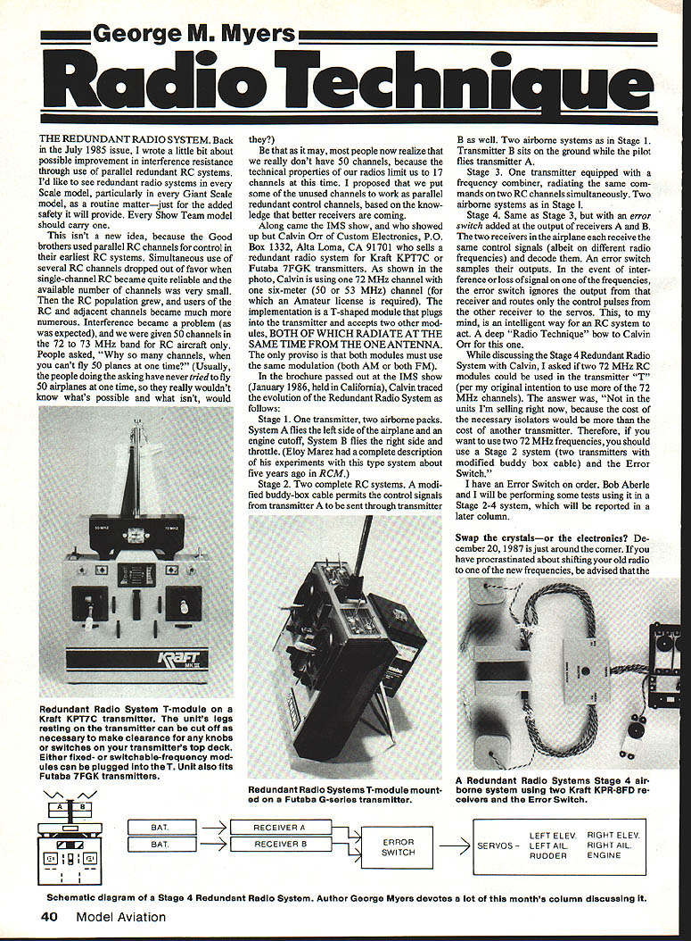
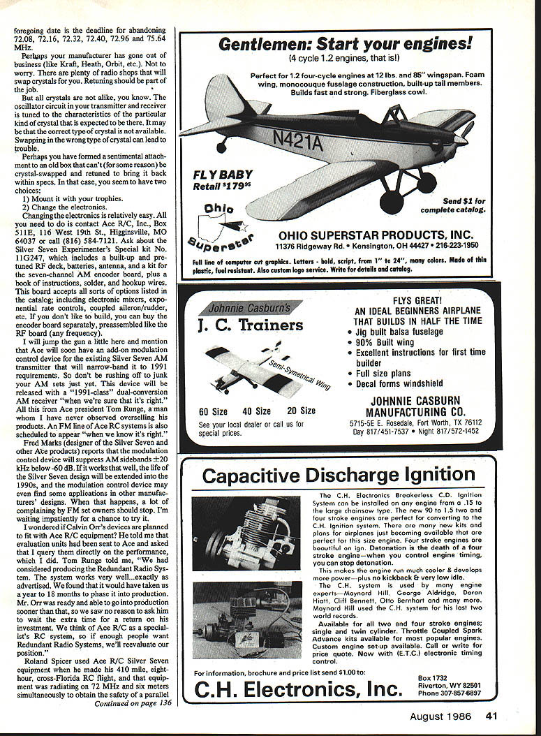
At the IMS show Calvin Orr of Custom Electronics (P.O. Box 1332, Alta Loma, CA 91701) displayed redundant radio systems for Kraft KPT7C and Futaba 7FGK transmitters. His T‑shaped module plugs into the transmitter and accepts two other modules, both of which radiate at the same time from the one antenna; the proviso is that both modules must use the same modulation (both AM or both FM). In Calvin's demo he used one 72 MHz channel and one six‑meter (50 or 53 MHz) channel (the latter requires an Amateur license).
Calvin traced the evolution of the Redundant Radio System as follows:
- Stage 1 — One transmitter, two airborne packs. System A flies one set of controls (for example, left side and engine cutoff) and System B flies the other set (for example, right side and throttle). (Eloy Marez described experiments with this type of system about five years ago in RCM.)
- Stage 2 — Two complete RC systems. A modified buddy‑box cable permits the control signals from transmitter A to be sent through transmitter B as well. Two airborne systems as in Stage 1; transmitter B sits on the ground while the pilot flies transmitter A.
- Stage 3 — One transmitter equipped with a frequency combiner, radiating the same commands on two RC channels simultaneously. Two airborne systems as in Stage 1.
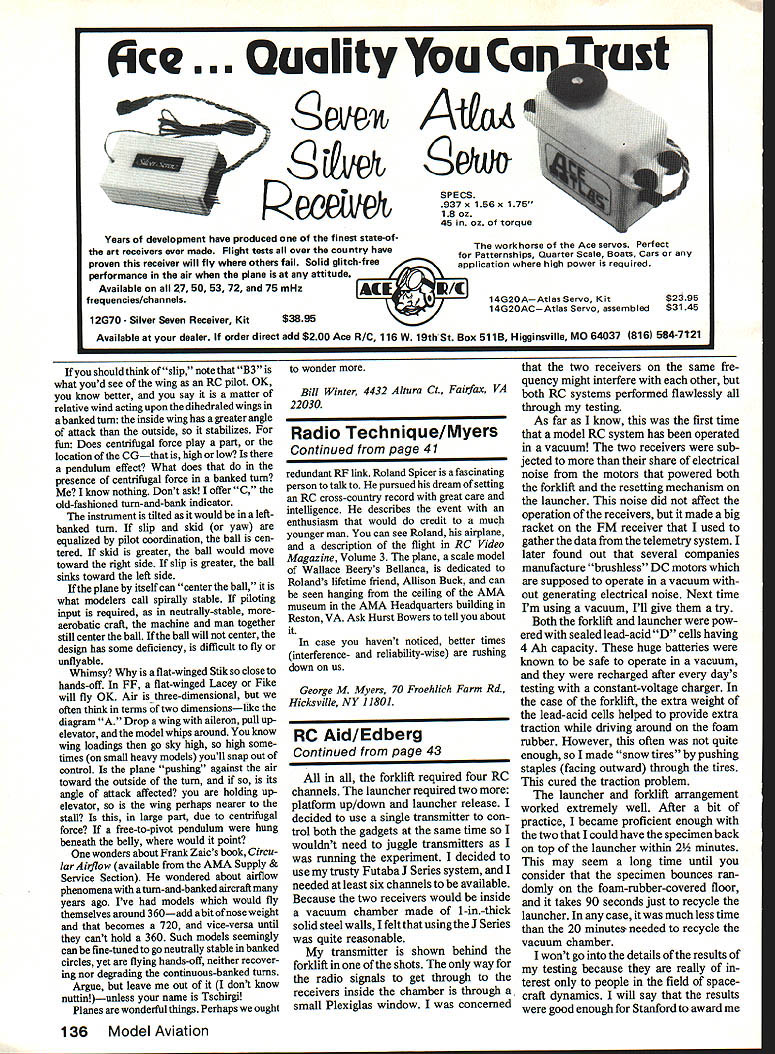
- Stage 4 — Same as Stage 3, but with an error switch added at the outputs of receivers A and B. The two receivers in the airplane each receive the same control signals on different radio frequencies and decode them. An error switch samples their outputs; if interference or loss of signal occurs on one frequency, the error switch ignores that receiver and routes only the control pulses from the other receiver to the servos. This is an intelligent way for an RC system to behave — a deep Radio Technique bow to Calvin Orr for this one.
I asked Calvin if two 72 MHz RC modules could be used in his transmitter "T" to take advantage of more 72 MHz channels. He said not in the units he's selling now because the cost of the necessary isolators would exceed the cost of another transmitter. Therefore, if you want two 72 MHz frequencies the recommended approach is Stage 2 (two transmitters with a modified buddy‑box cable) plus an Error Switch.
I have an Error Switch on order. Bob Aberle and I will perform tests using it in Stage 2–4 configurations and will report the results in a later column.
CRYSTAL SWAPS AND ELECTRONICS UPGRADES
December 20, 1987 is the deadline for abandoning the following frequencies: 72.08, 72.16, 72.32, 72.40, 72.96 and 75.64 MHz. If you've procrastinated about shifting your old radio to one of the new frequencies, have your crystals swapped at a radio shop — returning crystals should be part of the job.
But crystals are not all alike. The oscillator circuits in transmitters and receivers are tuned to the characteristics of particular crystal types. The correct type of crystal may not be available, and swapping in the wrong type can lead to trouble. If you have an old box that can't (for some reason) be crystal‑swapped back within specs, you have two choices:
- Mount it with your trophies.
- Change the electronics.
Changing the electronics is relatively easy. Contact Ace R/C, Inc., Box 511E, 116 West 19th St., Higginsville, MO 64037; phone (816) 584‑7121. Ask about the Silver Seven Experimenter's Special kit No. 11G247, which includes a built-up, pre‑tuned RC deck, batteries, antenna, and a kit for the seven‑channel AM encoder board, plus a book of instructions, solder, and hookup wires. The board accepts options listed in the catalog, including electronic mixers, exponential rate controls, coupled aileron/rudder, etc. If you don't like to build, you can buy the encoder board separately, preassembled (as is the RF board) in any frequency.
Ace president Tom Runge says Ace will soon offer an add‑on modulation control device for the existing Silver Seven AM transmitter that will narrow‑band it to 1991 requirements. This device is to be released along with a "1991‑class" dual‑conversion AM receiver when they're sure it's right. An FM line of Ace RC systems is also scheduled to appear when they are ready.
Fred Marks (designer of the Silver Seven and other Ace products) reports the modulation control device will suppress AM sidebands >20 kHz by below ‑60 dB. If it works that well, the Silver Seven design may be extended into the 1990s, and the modulation control device may find applications in other manufacturers' designs — which should quiet some complaints from FM set owners.
I asked whether Calvin Orr's devices are planned to fit with Ace equipment. Tom Runge said Ace had considered producing the Redundant Radio System and found it worked very well exactly as advertised, but that phasing it into production would have taken a year to 18 months. Mr. Orr was able to go into production sooner, so Ace chose not to delay him. Ace will reevaluate if enough people want Redundant Radio Systems.
Roland Spicer used Ace R/C Silver Seven equipment when he made a 410‑mile, eight‑hour cross‑Florida RC flight. That equipment radiated on 72 MHz and six meters simultaneously to obtain the safety of a parallel redundant RF link. Roland is a fascinating person; he pursued his cross‑country record with great care and intelligence and describes the event with an enthusiasm that belies his age. You can see Roland, his airplane (a scale model of Wallace Beery's Bellanca dedicated to his friend Allison Buck), and a description of the flight in RC Video Magazine, Volume 3. The plane can be seen hanging from the ceiling of the AMA Headquarters building in Muncie, IN — ask Hurst Bowers to tell you about it.
In case you haven't noticed, better times (interference‑ and reliability‑wise) are arriving even now in our area.
George M. Myers 70 Froehlich Farm Rd. Hicksville, NY 11801
Transcribed from original scans by AI. Minor OCR errors may remain.

