
George M. Myers
Radio Technique
Abstract
Accu‑Tach 2 — A review. Applications discussed: light levels, multiblade propellers, remote sensor, shunt resistances for R/C systems, peak‑detection charging.
Old Friend Revisited
I first reported on the Accu‑Tach 2 in the February 1985 issue of Model Aviation. It combines a digital voltmeter, ammeter, and tachometer in one compact package. My Accu‑Tach 2 has provided excellent service for years and is an essential part of my field kit.
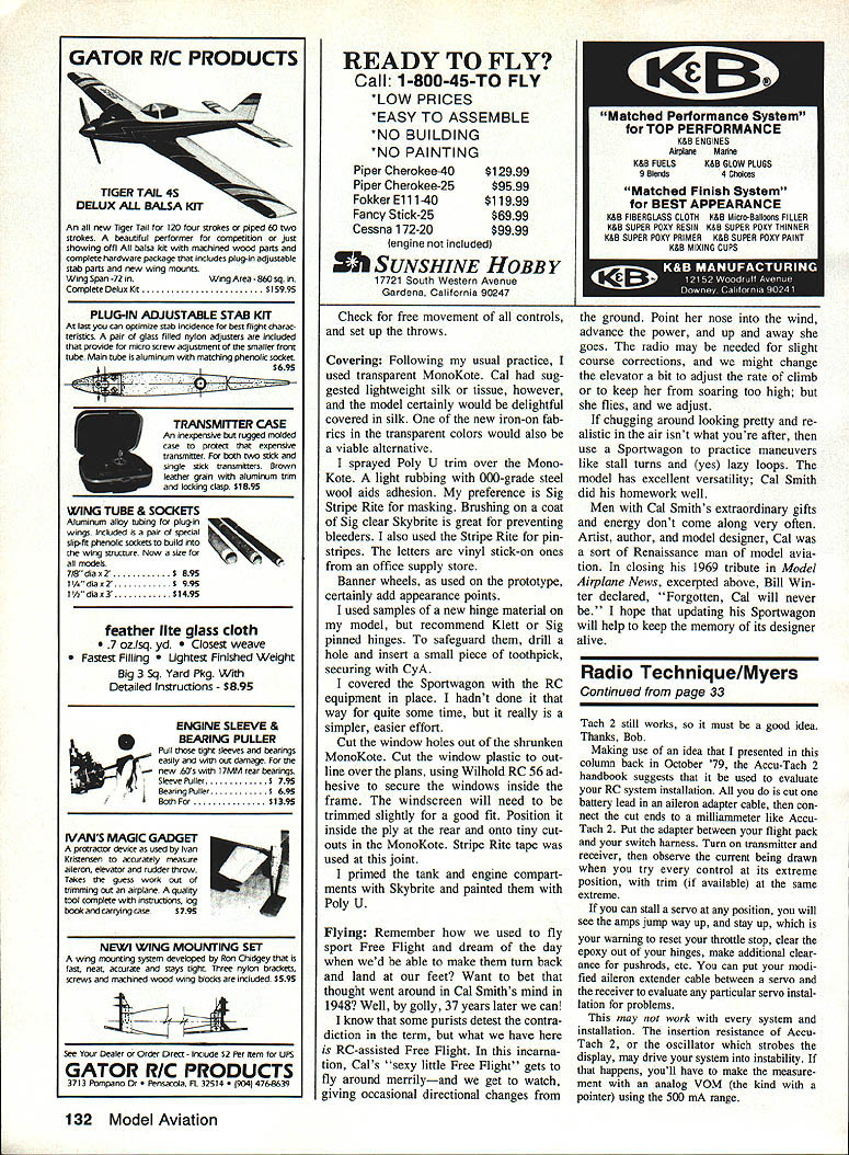
The unit is manufactured by Norcal Avionics, Div. of A‑B Tech Inc., 5689 Glasgow, Troy, MI 48098; telephone (313) 828‑8210. The Accu‑Tach 2A adds a remote tachometer probe, clip leads, and a zipper pouch. A couple of labels were added to clarify the Tachometer/Voltmeter selector switch and the built‑in tachometer sensor; otherwise it remains the same dependable instrument.
Accu‑Tach 2A Overview
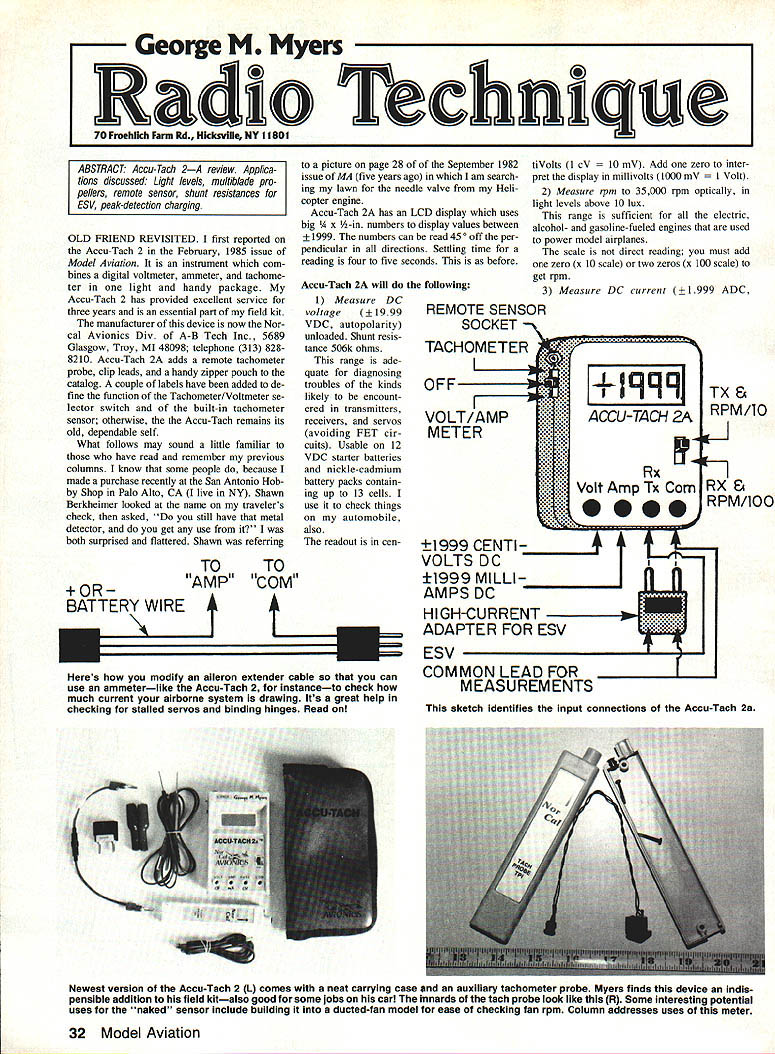
- LCD display with large 3/8‑in. digits showing values between ±1999 (autopolarity).
- Readable 45° off perpendicular in all directions.
- Settling time: 4–5 seconds.
Features
- Measure DC voltage
- Range: ±19.99 VDC (autopolarity).
- Unloaded shunt resistance: 506 kΩ.
- Adequate for diagnosing transmitters, receivers, and servos (avoid FET circuits).
- Usable on 12 V starter batteries and Ni‑Cd packs up to 13 cells.
- Indicates centivolts (1 cV = 0.01 V). Example: +478 cV = 4.78 V.
- Measure RPM optically
- Reads up to 35,000 rpm (optical) in light levels above ~10 lux.
- Two display scales: ×10 and ×100 (add one or two zeros to the displayed value).
- Counter handles up to 70,000 pulses per minute.
- True RPM = displayed value × scale factor (×10 or ×100) × (2/n), where n = number of blades. For a two‑bladed prop the 2/n factor = 1; for a single‑bladed prop multiply by 2.
- Measure DC current
- Range: ±1.999 A DC (autopolarity).
- Readout shows milliamps for lower values up to 1999 mA.
Tachometer
- Operation: Push the switch on the left side toward the tachometer "eye" on top of the case. Point the eye at the spinning propeller, keeping about a six‑inch clearance, and read rpm.
- Remote probe: Plugs into the side of the case. The remote optical probe fits through a 1‑1/4‑in. diameter hole; the sensor alone fits in a 1/4‑in. hole and can be built into a model (e.g., in a toroidal fan spinner).
- Light sensitivity: Minimum illumination for reliable readings is about 10 lux (measured with a Minolta Flashmeter II). Be careful of shadows and reflections — if the sensor sees them the reading will be too high.
- No dangerous contact with rotating machinery is necessary.
Milliammeter (Ammeter)
- Panel marked "Amp." but indicates directly in milliamps (useful for R/C work).
- Limited to ±1.999 A due to the 3½‑digit display (1,999 counts).
- Use: Helpful for checking stalled servos and binding hinges by observing current draw.
Suggested fuse modification:
- Per Bob Ahearn's suggestion, convert the red lead into a fused ammeter lead using a Radio Shack Inline Mini Fuse Holder (#270‑1238) with a 2 A fuse (#270‑1244).
- This adds about 0.4 Ω insertion resistance (may be too high for some tests) but provides protection. I have blown a couple of fuses myself.
Using the Accu‑Tach 2 as an Ammeter (Modifying an Aileron‑Extender Cable)
- Cut the aileron‑extender cable and insert a short piece of wire in the battery lead so the Accu‑Tach amp jack can be plugged in to measure current.
- The insertion resistance will be small; the meter then reads the current flowing into the receiver/servo installation.
- Procedure for monitoring receiver/servo current:
- Put the adapter between your flight pack and the switch harness.
- Turn on transmitter and receiver.
- Observe current when you move every control to its extremes (with trim at the same extremes).
- If a servo stalls, amps will jump and stay high — a warning to correct linkage, throttle stop, expo, etc.
- Cautions:
- The Accu‑Tach’s insertion resistance or volt drop may alter some servos' behavior.
- Some systems become unstable if receiver pack voltage is slightly reduced.
- If concerned, use an analog VOM with a 500 mA range instead.
Centivoltmeter
- The voltmeter displays centivolts (cV). Example: meter shows +478 cV → pack voltage = 4.78 V.
- Because it reads down to 10 mV (1 cV), it can be used for peak‑detection charging of Ni‑Cd packs.
Peak‑Detection Charging (Ni‑Cd)
- Method:
- Set a charging rate that will fully charge the pack in about 15 minutes.
- Watch battery terminal voltage during charge.
- When voltage, after rising, drops about 2 cV below the level it was a few seconds earlier, charging is complete.
- Warnings:
- High‑rate charging can ruin batteries if misused.
- Only charge when the pack is cool to the touch. The pack will warm but should never get hot. If it gets hot and stays hot, you have likely damaged the pack.
Expanded‑Scale Voltmeter and Built‑In Load Resistors
- Built‑in RX and TX positions select load resistors to apply a nominal load (~240 mA) useful for testing standard AA Ni‑Cd flight packs found in R/C systems.
- Indicates centivolts for precise battery testing.
- For low‑capacity packs (e.g., SR300), put the scale switch in "TX" position; current drawn will be about 120 mA.
- External shunts can be fitted for higher discharge currents when you wish to perform discharge tests (e.g., test a 1200 mAh pack at 600 mA). Shunt resistors will get hot — size accordingly.
Other Uses and Notes
- You can measure control pulses from the receiver to determine pulse polarity:
- Connect common lead to battery Negative.
- Connect Positive Volts lead to the signal lead (push a pin through servo pigtail if necessary).
- About 25 cV indicates positive‑going pulses; about 380 cV indicates negative‑going pulses (rare).
- The tachometer sensor and probe are handy for ducted‑fan models and other RPM checks where direct access is awkward.
- The Accu‑Tach 2A comes in a carrying case with an auxiliary tachometer probe; the probe plug resembles an RCA phono plug.
Final Notes
- The Accu‑Tach 2A remains a versatile, handy instrument for field and bench work on model aircraft and related electronics. Use the instrument within its limits and follow cautions for charging and ammeter insertion effects.
Transcribed from original scans by AI. Minor OCR errors may remain.

