
Radio Technique
By George M. Myers
70 Froehlich Farm Rd., Hicksville, NY 11801
Abstract
A revised Myers/Aberle test procedure is described, and the results of testing the Polk's Aristocraft/High-Tec Challenger 720 and the Ace R/C Model 91 are given.
RC System Testing
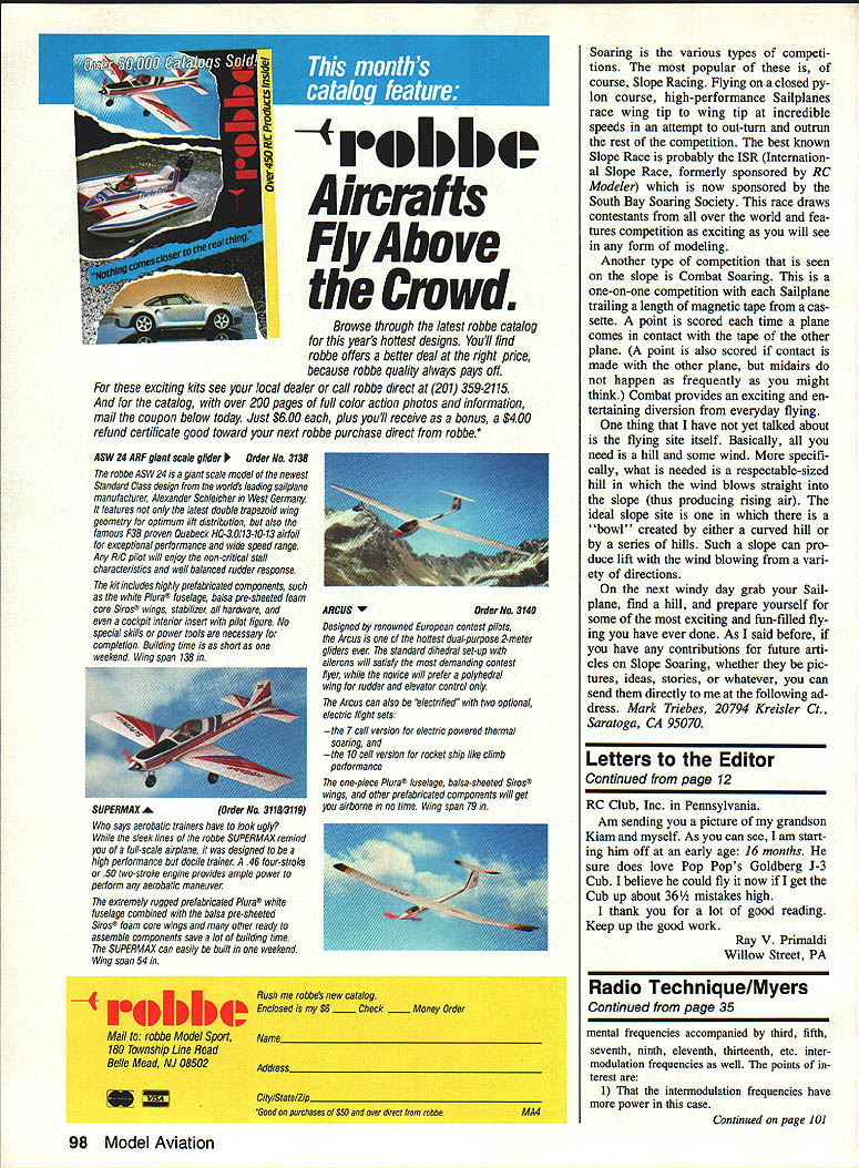
Bob Aberle and I have modified our test procedure (originally published in my January 1986 column) slightly to match the 1988 situation. Our new test matrix requires that the transmitter is at least −50 dB at F0 ±20 kHz.
OWBAM transmitters (old wideband AM)
- We use George Steiner–modified Kraft synthesizer modules. These produce AM signals with sidebands of about −35 dB at F0 ±20 kHz with 500 Hz frequency accuracy.
- They radiate slightly less power than the NBFM synthesizers.
- None of the synthesizers will produce RC40, so our test matrix must work around that limitation at times.
- The power output difference between the AM and FM Kraft modules must be considered.
To include specific tests differentiating between interference from 1988 narrow-band AM transmitters and interference from old wideband transmitters (OWBAM), the modified procedure uses several pieces of test equipment recalibrated especially for this procedure.
NBFM transmitters (narrow-band FM)
- We use Kraft transmitters with synthesized RF (the out-of-production, switchable-radio-frequency modules).
- These FM modules have been tested by George Steiner and reported to be at least −55 dB at F0 ±20 kHz, with frequency accuracy better than 500 Hz.
NBAM transmitters (narrow-band AM)
- We use Bob's Tower Hobbies Gold 500 transmitter with a pocket full of special crystals, individually checked for frequency accuracy by George Steiner.
- We don't have a full set of crystals for the Tower transmitter, which provides a further limitation. While our test tools aren't perfect, the same tools are used on every test, so the results should be a fair comparison. We can proceed with field testing as before, using what we have.
Except for the matrix and equipment changes, the procedure remains as I described in the January 1986 issue of Model Aviation (page 42 et seq.).
The FLS Test (formerly "31M")
A long time ago we started using the term "31M" to describe a particular kind of test where the interfering transmitters are placed butt-to-butt. The term "31M" was poorly chosen. In the future, we will refer to that test as "FLS" (Flight Line Simulation), and here's why:
When I was concentrating on creating a field test for third-order intermodulation interference that could be performed without special test equipment, the FLS (formerly 31M) setup proved useful. The FLS setup does generate third-order intermodulation products; it also generates other useful signals.
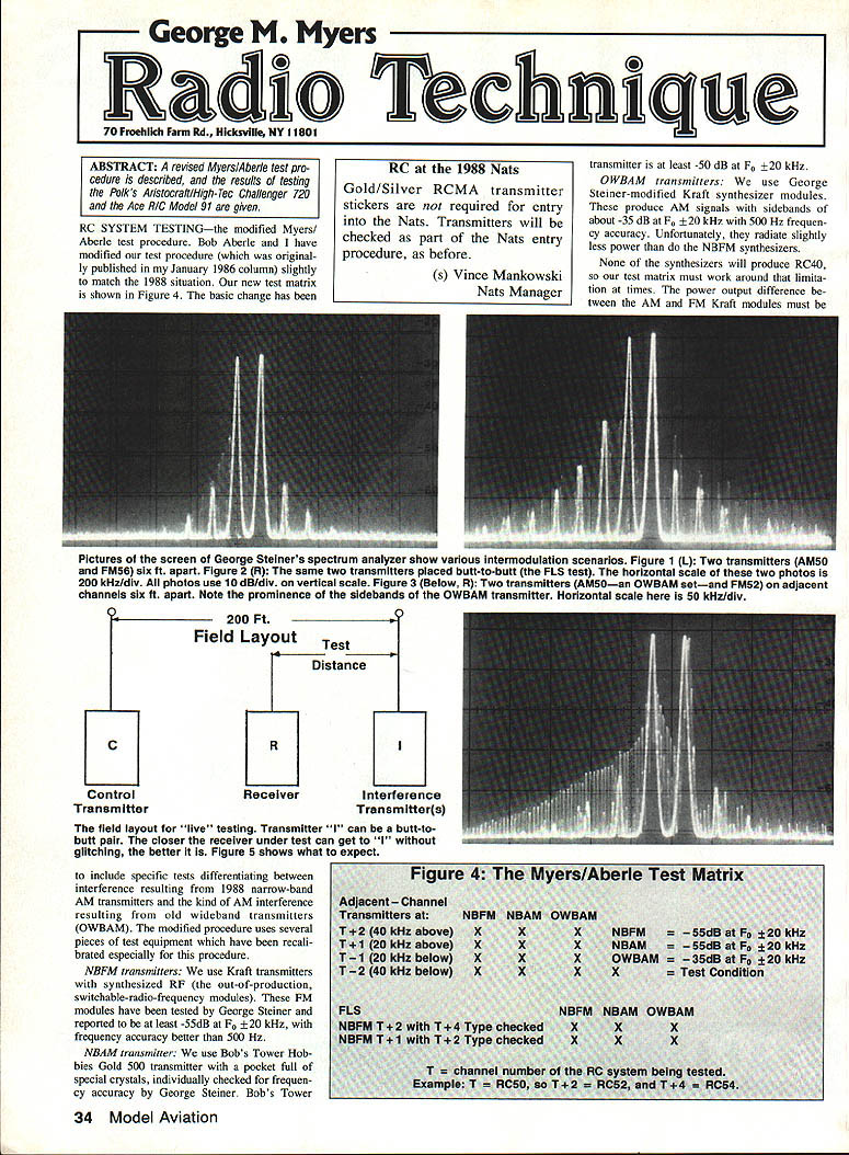
Figures in the original column show George Steiner's spectrum analyzer screen when two transmitters—a silver-sticker AM transmitter on RC50 and a gold-sticker FM transmitter on RC56—are placed six feet apart (antennas parallel) and butt-to-butt (antennas coaxial). With antennas parallel, third-, fifth-, and seventh-order intermodulation signals are generated inside the spectrum analyzer; in receivers they appear as tiny spikes riding low shoulders of the primary signals.
But when the transmitters are placed butt-to-butt, everything changes: the intermodulation signals (which are generated inside the transmitters as well as inside the receiver) are much stronger and consist of the fundamental frequencies accompanied by third-, fifth-, seventh-, ninth-, eleventh-, thirteenth-, etc. intermodulation frequencies as well.
Points of interest:
- The intermodulation frequencies have more power in this case.
- They may fall directly in the centers of adjacent RC channels.
- They are spaced the same as the two generating transmitters (in the example, intermodulation-generated channels are spaced 120 kHz apart because the generating transmitters are spaced 120 kHz apart).
This is a pretty good simulation of flying near a crowd of RC transmitters operating on adjacent channels—it has the advantage that you don't need a crowd of transmitters for the simulation. From now on we will call the butt-to-butt test setup an FLS (Flight Line Simulation) test.
The FLS test is an easy way to discriminate between receivers that show good resistance to saturation from a crowd of adjacent-channel transmitters and those that don't. Based on George Steiner's data from tests of hundreds of RC receivers, the best designs sold prior to 1988 won't tolerate an interfering signal more than about 30 dB above the minimum signal required for good control. This is true whether the interferer is 10 kHz or 500 kHz away.
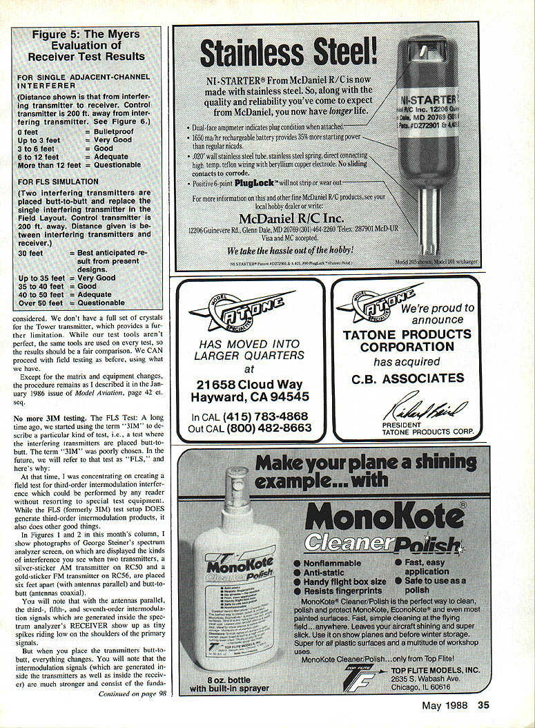
The 30 dB power level translates to a minimum FLS test distance of about 30 ft when the receiver is between the interferers and the control transmitter that is 200 ft away, as in our test setup. This yields a multiplier of (200 − 30) / 30 = 5.67. Remember that number.
Our intention remains to present a simple field test that looks at the worst case and doesn't need special test equipment. The worst case occurs when you stand alone, a couple of hundred feet from a crowd of transmitters operating on adjacent channels.
In practice, some people can stand side-by-side in a group and fly without obvious interference problems because they have good transmitters and receivers. Crowding transmitters together creates ideal conditions for adjacent-channel interference, particularly for OWBAM RC systems designed for an 80-kHz matrix that were operating in a 40-kHz matrix.
Figure 3 (original column) shows what happens when you put an OWBAM transmitter next to a new FM transmitter operating one channel (40 kHz) away: the intermodulation signals (which identify the other adjacent channels) are buried in the sidebands of the relatively sloppy AM transmitter. Three‑order intermodulation isn't the only problem when you are standing close and flying—the OWBAM transmitter's sidebands are a major issue. As better transmitters replace OWBAM transmitters, interference problems on the 40 kHz raster (especially that part instituted for 1988) should become rare.
However, "spreading out" pilots on the flight line creates its own problems. If you are at one end of a long line of pilots, your airplane must fly close to other transmitters when taking off or landing. That can make both adjacent-channel and third-order signals strong enough to cause glitches at a critical point in your flight. What might have been only a dip during a fly-by becomes a serious deviation close to the ground.
Owen Black's "Pacific Plan," which separates 3IM pairs by 60 ft or more on the flight line (thereby reducing all possible intermodulation signal power to insignificant levels), has proven to be all you need to avoid this problem.
Field Testing Results
Bob and I have spent time testing a small group of RC systems using the revised procedure. The results from five different system tests show some interesting things.
- The bad news: OWBAM interference is always the worst, particularly for 20 kHz adjacent-channel interference.
- The good news: OWBAM interference should begin to disappear as OWBAM transmitters are replaced.
- Paragraph 3.1.4 of the AMA Frequency Use Plan already prohibits any OWBAM transmitter within 20 kHz of another transmitter—this is true right now.
We test for OWBAM because in 1991, when we go to all 50 channels spaced at 20 kHz, someone at the local field might still be operating an OWBAM transmitter on RC38–RC56 that hasn't been upgraded since 1982. That's why we test for it.
Receivers that passed the new tests
- Polk's Aristocraft/High-Tec Challenger 720 (FM receiver)
- Scored "bulletproof" against all three types of single adjacent-channel transmitters at both 20 and 40 kHz.
- Scored "Very Good" against FLS at 20 and 40 kHz.
- The transmitter meets AMA requirements for use on "any channel."
- This is a low-priced system and one of the best receivers we've tested.
- Polk's Modelcraft Hobbies, 3456 Bergen Ave., Jersey City, NJ 07304; telephone 1-800-225-POLK.
- Ace R/C Model 91 (AM dual-conversion receiver)
- Scored "Very Good" against all three types of single narrow-band adjacent-channel transmitters at 20 and 40 kHz.
- Scored "Very Good" against FLS at 40 kHz.
- Ace R/C, Inc., Box 511E, Higginsville, MO 64037; telephone (816) 584-7121.
What does that mean in the real world?
- The Polk's Aristocraft/High-Tec Challenger 720 should work fine on any RC aircraft channel now and beyond 1991.
- The Ace R/C Model 91 should do well against the 1988 narrow-band environment that will exist in RC12–RC34 (if the community implements it) and in the narrow-band environment planned for 1991 and beyond.
It's still all up to you!
Transcribed from original scans by AI. Minor OCR errors may remain.

