
Radio Technique
Abstract
George Steiner's procedure for using the ICOM IC-R7000 receiver to spot-check transmitter sidebands is given.
Background
It isn't cheap, but it is cheaper. Where a Contest Director for an RC meet once only needed a scanner to verify that the flag on a contestant's transmitter matched the transmitter's operating frequency, now the director may also want to verify transmitter power levels. The AMA rule book authorizes the Contest Director to make whatever measurements are necessary to ensure a contest does not create unnecessary risks for contestants.
Section 3.4 of the "AMA Guidelines for Narrow-Band Operation of 72–75 MHz Radio Control Frequencies" (hereafter "AMA Guidelines"), published in the September and October 1987 editions of AMA News, calls for a transmitter frequency tolerance of ±1,500 cycles in the 72 MHz band.
The AMA Guideline for a narrow-band transmitter calls for −55 dB at F0 ±20 kHz. This requires three discrete power-level measurements: one at the transmitter's operating frequency and one at each of the frequencies 20 kHz away from that frequency.
Obviously, you need a way to measure frequency accurately and a way to measure power at a discrete frequency. This requires three things:
- A frequency-measuring device that is traceable for accuracy back to the National Bureau of Standards (NBS) and that has frequency stability better than 10 parts per million (ppm). At 72 MHz and 10 ppm, the signal may drift about 720 Hz between measurements.
- A narrow-band receiver to separate the power in a specific band of frequencies from the rest of the transmitted power. (Note: we speak here of a band of frequencies, not true power at a discrete single frequency.)
- A power meter. Ideally this is an absolute power meter traceable to the NBS; in practice a relative-power meter is usually sufficient and easier to obtain.
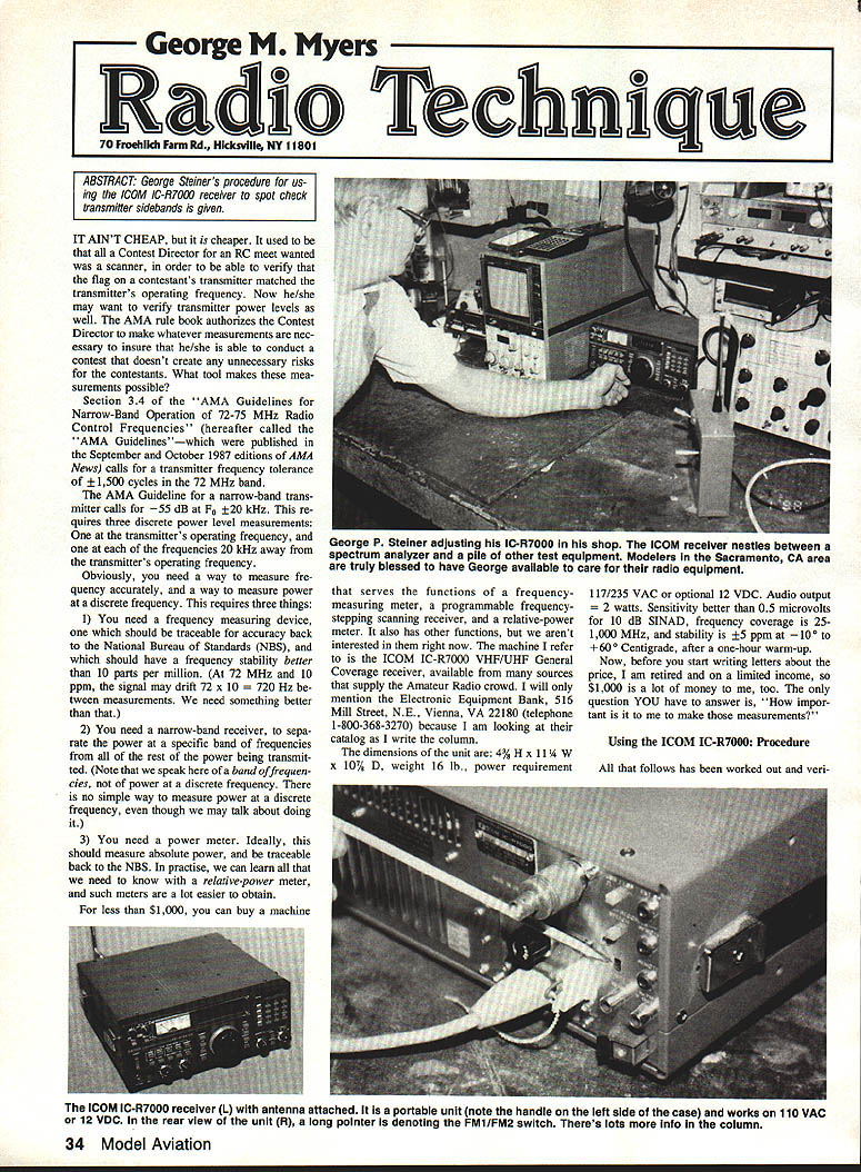
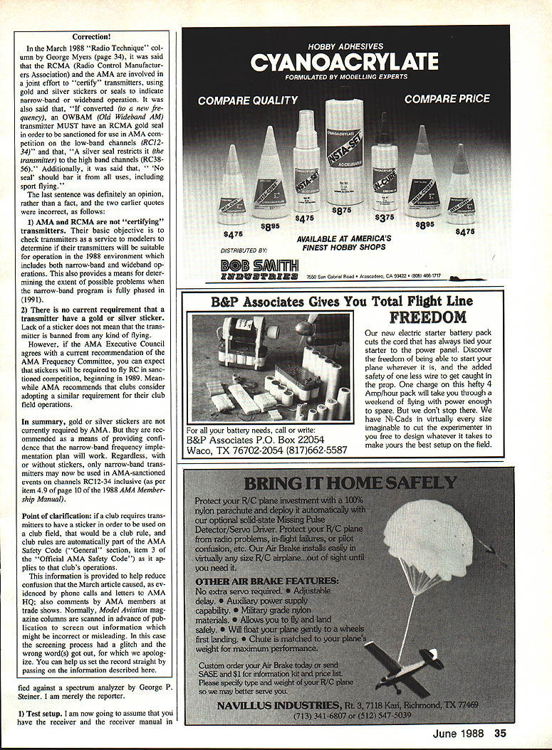
For less than $1,000 you can buy a machine that serves as a frequency-measuring meter, a programmable frequency-stepping scanning receiver, and a relative-power meter. The machine described here is the ICOM IC-R7000 VHF/UHF General Coverage receiver, available from many Amateur Radio suppliers. (Example vendor: Electronic Equipment Bank, 516 Mill Street, N.E., Vienna, VA 22180; tel. 1-800-368-3270.)
Specifications (manufacturer):
- Dimensions: 4½" H × 11¼" W × 10¾" D
- Weight: 16 lb
- Power: 117/235 VAC or optional 12 VDC
- Audio output: 2 watts
- Sensitivity: better than 0.5 µV for 10 dB SINAD
- Frequency coverage: 25–1000 MHz
- Stability: ±5 ppm at +60°C after one-hour warm-up
Now, before you consider price: the only question is what is important to make these measurements. Using the ICOM IC-R7000, the procedure follows.
All that follows has been worked out and verified.
Procedure (using the ICOM IC-R7000)
- Test setup
- Place the test setup on a wooden table.
- Connect a 50-ohm unbalanced antenna to the BNC jack on the back of the ICOM receiver and extend it to full length. Support the antenna vertically at the test table.
- Place the RC transmitter to be measured on the table with its antenna fully extended and parallel to the receiver antenna, about three feet away.
- Set up the receiver switches
- Ensure the FM1/FM2 switch on the back panel is in the FM1 position (gives the narrowest bandwidth to the receiver, −6 dB at F0 ±3 kHz).
- Select FM on the right-hand panel.
- Set RF Gain to the nine o'clock position and Squelch to 12 o'clock.
- Power-up and warm-up
- Turn on the IC-R7000 and allow it to operate for about one hour before making measurements to ensure stable, repeatable readings.
- Prepare the transmitter
- Turn on the transmitter to be tested. Ensure the batteries are fully charged and the antenna is fully extended.
- Tune the receiver to the transmitter frequency
- Put the meter switch in the "C" position and find the frequency. Check that the needle swings about one-quarter of the scale when you rock the tuning knob.
- Put the meter switch in the "S" position and slide the test transmitter around on the table until the meter reads +40. This establishes the distance between antennas that produces a +40 (reference) reading.
- Check the sidebands
- Without changing the test-transmitter position, rotate the tuning knob to change the displayed frequency by 20 kHz (raise or lower the displayed number by 20). Note the meter reading at both positions.
- If the needle reads between 1 and 6 on the dial, the transmitter is narrow-band and may rate a Gold sticker for use on channels RC12 through RC34.
- If the needle reads between 6 and 10 on the dial, the transmitter is wideband, would rate a Silver sticker, and would be suitable only for channels RC36 through RC56.
- If the needle reads between 10 and +60 on the dial, the transmitter does not qualify for any sticker.
- Repeat steps 4 through 6 for each transmitter to be tested.
Calibration and accuracy
Calibration of the IC-R7000 is specialized work and should be done only by persons with the right equipment and experience. Errors in calibration can be numerous. Two instruments known to the author were calibrated when purchased and were within 10% of the readings reported above. Another instrument checked after one year in service showed a 10% change in the meter calibration. Such variation could cause transmitters that actually qualify for a Gold sticker to be reported only as Silver.
Conclusion
The ICOM IC-R7000 is good enough for local-club use as a scanner to find and identify transmissions in the RC bands (except the 27 MHz band) and can be accurate enough to find transmitters outside the AMA frequency tolerances. When it comes to measuring power levels for installing Gold and Silver stickers, it is not sufficient—paragraph 3.2.2 of the AMA Guidelines requires a spectrum analyzer for that purpose. However, the ICOM is good enough to reveal illegal crystal swapping, and that is often all a Contest Director really needs to know.
Transcribed from original scans by AI. Minor OCR errors may remain.

