
Radio Technique
George M. Myers 70 Freehlich Farm Rd., Hicksville, NY 11801
CORRECTION: The correct telephone number for TRC Engineering is (616) 453-8527. An incorrect number was given last month.
Abstract
Reply to criticism of June 1988 column. 1988 Pacific Plan for aircraft and surface use. Replacing transmitter batteries.
Reply to criticism
The author of a recent column in another modeling publication took me to task about certain things I said in my June 1988 "Radio Technique" column. The specific criticisms were that I had called RC crystal swapping "illegal," and that I had claimed that the ICOM IC-R7000 receiver was not good enough to use in measuring transmitter power levels in the tests necessary to certify that a transmitter meets the AMA/RCHA "Gold Sticker" or "Silver Sticker" performance tolerances—and that I was not technically qualified to make the latter statement.
- I used the expression ". . . to reveal illegal crystal swapping . . ." Crystal swapping which produces off-frequency radiations and/or excessive power in the sidebands is illegal, and the ICOM can detect this. I did NOT say that crystal swapping, of itself, is illegal.
- It is not MY opinion that the ICOM receiver is an unacceptable instrument for determining whether a transmitter's radiations are within limits acceptable to the AMA Guidelines. This was the opinion of expert witnesses at a recent AMA Frequency Committee meeting which I attended. Yes, I admit that I didn't say as much in my column, but what I DID say had a solid basis in fact—and I got the information firsthand.
I hope this discussion will put to rest any further exchanges in print relating to this matter.
Pacific Plan for 1988–90
Since the beginning of the year I have been receiving requests from readers for a 1988 "Pacific Plan." Each letter, without fail, mentions that the club in question has been using the Pacific Plan presented previously, and that incidents of RF problems have been noticeably less than before. In some letters, readers also state that when they fly at places without the plan, RF interference incidents are more numerous than at their home field. So there must be people out there who have actually used the plan and found it valuable.
The existing Pacific Plan (which depends on a 25-ft. space between flight stations) can be used for RC38–56. If use of channels RC12–34 is restricted to transmitters and receivers that conform to the AMA Guidelines, then no special arrangements should be needed on the low end of the band and a five-station set-up such as Table 1 shows. I have scattered RC12–34 around according to the Pacific Plan and I have found that it will reduce the kind of interference that might be caused by someone using a phony Gold Sticker on the low channels.
Once again, credit Owen S. Black and George P. Steiner (both from the Sacramento, CA area) for inventing the Pacific Plan. All I have done is make use of it.
I have received several letters asking about special arrangements for sharing flying fields with boats and cars. Typical is one from Michael D'Amico of the Indian River RC Society (Palm Bay, FL). I remember Mike as a young man in the LIRCS, going off into the Air Force back in 1972. Michael writes: "The county has 100 acres and wants a new idea for a recreational park. If we have RC boats, cars, and planes all running at once, we may run into frequency problems not previously encountered. Can you help?" — Michael D'Amico
This is a complicated question. Let's answer it piece by piece:
First, the 75 MHz transmitters should not pose any problem for the aircraft on 72 MHz, and vice versa. So any setup that keeps people out of the "Strike zone" (the flying area—see Page 2 of your 1988 AMA Membership Manual) is okay. The Pacific Plan "Drivers' Line" setup for 75 MHz shown in Table 2 is feasible, but I wonder if anyone would follow the suggestion.
Table 2 — 75 MHz — Surface Only No stickers — 40 kHz raster Station: A B C D E Row 1: 62 76 64 78 68 Row 2: 70 82 72 80 84
The 27 MHz, 50 MHz, and 53 MHz channels are FCC-legal for either aircraft or surface vehicles. This poses a problem. There are several possible solutions:
- You might, as George Steiner suggests, have a single impound area for all transmitters. Then it may not matter what purpose pins are used for. I anticipate that the park people will want to run an impound because it will give them optimal control of everything.
- You might set up some kind of frequency assignment scheme peculiar to the park, such as even channel numbers for aircraft and odd numbers for surface use (Ham and CB only).
- You might ask the modelers to surrender the 27 MHz frequencies to the surface people, and ask the Hams to use RC00–09 for Aircraft Only and 53 MHz for Surface Only. Your club may find other acceptable solutions.
As far as 27 MHz is concerned, there are voice channels ±10 kHz from the RC channels. Mobile CB activity has dropped off in many parts of the country to a point where RC aircraft fly without significant problems. But I live on a metropolitan island, 30 miles wide and 120 miles long. I can't use my mobile CB for anything in summer because traffic on all channels is heavy. Much of it is boat-to-boat, some is truck-to-truck, and the balance is kid-to-kid. A new generation of motor-mouths has sprouted, and I hear them all over the New England states.
Illegal CB power amplifiers have almost disappeared, but from time to time I still hear one transmitter on 10 adjacent channels. Even RC sailboats in the pond are interfered with occasionally. So I don't try 27 MHz RC on Long Island, NY. Buy a crystal-controlled CB, plug in an RC receiver crystal, and use the CB as a monitor if you intend to do any flying on 27 MHz. In Table 3 I have distributed the 27 MHz channels according to the Pacific Plan. I even threw in 27.255 MHz, but would anyone be dumb enough to use it, considering the high power levels allowed to "other users" on 27.255 MHz?
Table 3 — 27 MHz Citizen's Band — Aircraft and Surface Use No transmitter stickers — 50 kHz raster Station: A B C D E 27.025 27.055 27.085 27.045 27.195
There can be voice transmissions at any kHz displacement from a Ham RC channel. Hams are required to listen before they transmit, which tends to limit RFI interference, but there are no guarantees. Any quiet spot in the band can be used by a Ham operator.
Changing gears, I used the Pacific Plan to distribute all of the Ham-band R/C 50-odd channels as shown in Table 4, because they are on a 20-kHz raster, and because I expect most current users can obtain Gold Sticker performance. The Hams should get together on this group and insist on moving everything to Gold Sticker as soon as possible—certainly by 1991.
AMA only permits the even-numbered channels in sanctioned events, but the Hams are at liberty to use all 10 of them right now at your park, which makes Gold Sticker performance necessary for safe operation.
Table 4 — 50 MHz Ham Band (20-kHz raster) Aircraft / Surface / Communications Uses Station: A B C D E Row 1: 00 03 01 04 02 Row 2: 07 05 08 06 09
The 53 MHz (six-meter) distribution in Table 5 is per the Pacific Plan, but may not be necessary due to the 100-kHz raster.
Table 5 — 6-Meter Ham Band (100-kHz raster) Aircraft / Surface / Communications Uses Station: A B C D E Row 1: 53.3 53.1 53.4 53.2 53.5 Row 2: 53.6 53.7 53.8
Replacing transmitter batteries
How many times have you noticed that your transmitter output meter reads lower than usual and/or that operating time is shorter than it used to be? The most common problem is that one cell in the battery pack has developed a short circuit.
If the transmitter is still under warranty, you probably send it back to the manufacturer and wait. But it may be out of warranty and you don't want to wait. Decision time: do you find and replace the bad cell, or do you replace the whole pack?
To make that decision you must remove the pack from the transmitter.
- Step 1: Disconnect the pack. Of all the mistakes you can make when working on an electronic circuit, the least forgivable is to disconnect components because you were too lazy to disconnect the power supply. A momentary short circuit in the wrong place can destroy your transmitter's electronics. So unplug and remove the battery pack, and cut both wires if you can't remove it cleanly.
- Step 2: Reconnect convenience. It is simple to put Deans connectors (19K54, $1.55 from Ace R/C, Inc., Box 511E, Higginsville, MO 64037) on the end of the wire when you reassemble the transmitter. Match the wire colors when you install the Deans connectors (making sure that the male plug side is on the transmitter), and pull the pins out of the isolated contact to provide a quick visual check so you don't connect the battery pack with reversed polarity.
On the matter of polarity: practically everyone uses Red for + and Black for −. Larry Brinick told me that in the case of PCM transmitters from Futaba and JR only, the Red wire on the charger is − and the Black wire is +. A voltmeter is a necessary tool when working with batteries—don't assume anything!
Now that you have the pack in your hand, mark each cell with a pen or paper sticker. Then attach a 20-ohm/10-watt resistor to the pack and monitor the voltage of each cell as the pack discharges. Write down the voltages for each cell at five-minute intervals. Keep discharging the pack until each cell reads 0 VDC. Leave the resistor connected (it won't hurt anything).
Looking at the list of voltages will tell you which cell is shorted (it will start at 0 VDC) and whether the pack is balanced (all cells reach 0 VDC at about the same moment) or unbalanced (they don't). If the pack is unbalanced, remove the resistor and place the pack on the charger overnight to recharge. If the pack is still unbalanced, my suggestion is to junk it—another cell is probably going to fail. Ace R/C sells Ni-Cd packs and probably can supply what you need.
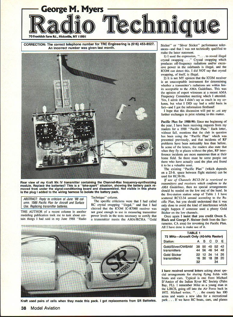
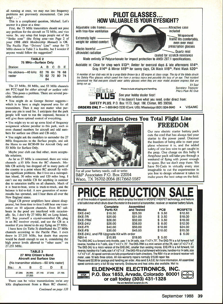
If the pack is balanced and only one cell is shorted, it probably makes sense to replace the bad cell (or pair of cells, if packaged that way). As you can see in the pictures, the cells in my Kraft synthesizer transmitter were packaged in pairs, but I replaced the whole pack. I need that transmitter for the Myers/Aberle tests.
If you want the best, contact my friend Larry Brinick of SR Batteries, Box 287, Bellport, NY 11713; (516) 286-0079. SR can and will supply packs with connectors for equipment manufactured by Ace R/C, Airtronics, Cannon, Cirrus, Cox/Sanwa, Futaba, Kraft, Tower, some World Engines, and anything with a Deans connector.
If you can't find a source for the manufacturer's connector, you can always use Deans connectors or contact SR for help. For example, I haven't been able to find a source for the Hi-Tec connector used by Polk's and World Engines, so I use the Deans.
As for the cells themselves, SR will suggest alternates (e.g., SR900s in place of 500s) and will make up packs in special configurations (any number of cells, "L" shapes, stacked packs, etc.). They keep an up-to-date file of original transmitter battery pack configurations and can make up virtually any pack you need.
Though they don't like doing it, SR will replace individual cells in your pack for you—charging only $2 over the cost of materials—and giving your pack the full five-day test sequence to ensure it is worthy of continued use.
Some manufacturers make battery pack replacements a simple plug-in matter (Airtronics), while others make it a "take-apart the transmitter" affair, as was the case with my Kraft. If you are at all hesitant about making the change, turn the problem over to a serviceman. Check the warranty first.
I'm still on vacation. Happy flying!
Transcribed from original scans by AI. Minor OCR errors may remain.

