
Radio Technique
George M. Myers 70 Froehlich Farm Rd., Hicksville, NY 11801
Abstract
Polk's Challenger 550 PCM radio system.
Big News
Polk's is moving toward an all-PCM line for its radio gear. This is a positive move because PCM offers better performance on several levels:
- PCM makes a significant improvement in resistance to all forms of interference. This is due to the way the PCM receivers' computers use sample-and-hold to compare new information with old information to detect interference.
- Most PCM systems, Polk's included, use a Hold feature to provide a failsafe set of positions for the servos. This is an advantage over pulse-width systems (our common AM and FM sets), which almost always drive servos toward the short-pulse end of travel whenever interference occurs. That behavior is what causes AM/FM systems to produce the familiar snap-roll-and-spin-down.
- The more PCM systems on the market, the wider the choice and the lower the prices.
Challenger 550 Overview
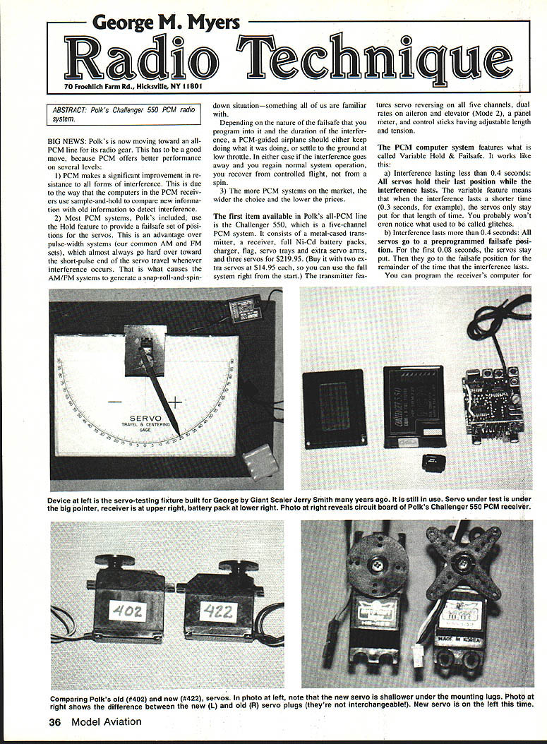
The first item available in Polk's all-PCM line is the Challenger 550, a five-channel PCM system. The package includes:
- Metal-cased transmitter
- Receiver
- Full Ni-Cd battery packs
- Charger
- Flag servo trays and extra servo arms
- Three servos
Price: $219.95 (option to buy with two extra servos at $14.95 each so you can use the full system right from the start).
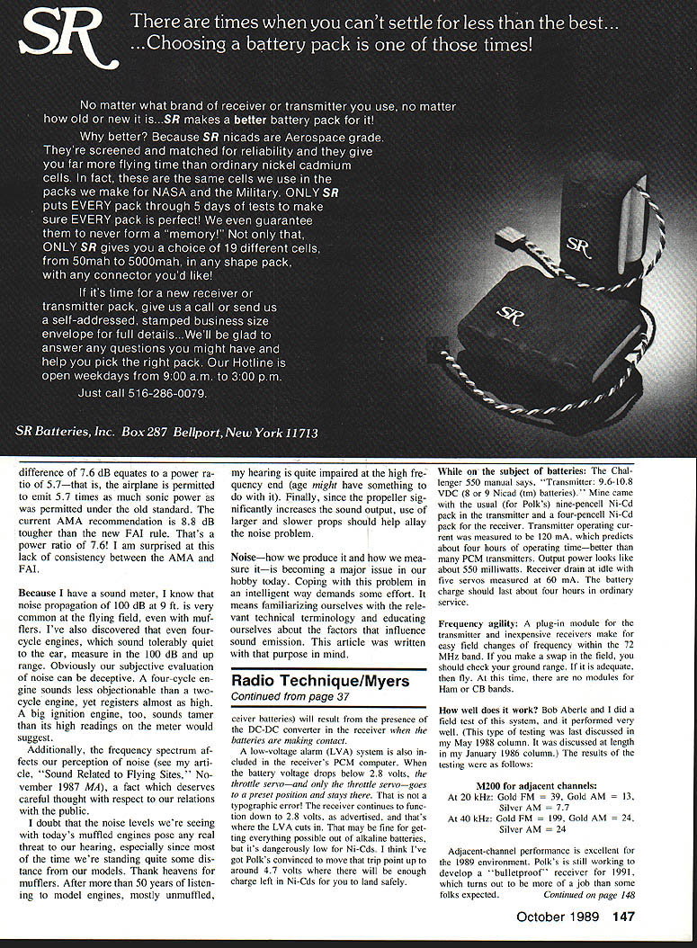
Transmitter features:
- Servo reversing on all five channels
- Dual rates on aileron and elevator (Mode 2)
- Panel meter
- Control sticks with adjustable length and tension
PCM Computer Features
Variable Hold & Failsafe
The PCM computer system features "Variable Hold & Failsafe":
- a) Interference lasting less than ~0.4 seconds: All servos hold their last position while the interference lasts. The variable feature means that when the interference is shorter (e.g., 0.3 seconds), the servos only stay put that length of time. You probably won't even notice what used to be called glitches.
- b) Interference lasting more than ~0.4 seconds: All servos go to a preprogrammed failsafe position. For the first ~0.08 seconds the servos stay put, then they move to the failsafe position for the remainder of the interference. You program the receiver's computer for the desired failsafe positions by pushing a button while the transmitter is operating. For example: take the plane up, reduce throttle to idle, trim for a wide, slightly descending circle, then press the button while the plane is circling to store that position in the receiver's computer.
When the interference ends, recovery timing is roughly two frames (one frame is the time for the computer to perform one complete cycle of program execution). Two frames are about 0.14 seconds; the servos then start back toward the transmitter-commanded positions. If they have to travel to the opposite end of travel, it could take another ~0.2 seconds at a battery voltage of about 6 volts. So you will be out of control roughly 0.3–0.35 seconds longer than the duration of the interference—about the same as a non-PCM system, but you recover to controlled flight rather than from a spin.
Programming Failsafe
You choose failsafe servo positions by pushing a button on the transmitter while the system is operating, as described above. Stored positions will be used during extended interference until normal operation resumes.
Receiver, Power, and Stability
- The receiver in the system is a dual-conversion design similar to last year's Challenger 720, with a PCM computer added. Performance is very good.
- Receiver operating range: 2.8–7.0 volts. The seven-volt rating means the receiver will work with a five-cell Ni-Cd pack, providing faster servo speed and greater torque.
- The receiver uses an Automatic Gain Down system (automatic gain control) that reduces amplification when the control signal is strong, helping to tune out other potentially interfering signals.
- A DC-to-DC converter in the receiver provides very stable performance as battery voltage varies over the 2.8–7.0 V range.
Alkaline Batteries and "Flashlight Syndrome"
Polk will likely permit use of alkaline batteries in the receiver for cars or boats, but I strongly advise caution for aerial use with a four-cell alkaline pack. You may encounter the "flashlight syndrome"— intermittent contact where a battery pack appears to work only after jarring. That same intermittent contact can occur in an airplane and cause loss of control. The DC-to-DC converter helps mitigate contact-related problems when batteries are making good contact.
Low-Voltage Alarm (LVA)
A low-voltage alarm is included in the receiver's PCM computer. When battery voltage drops below 2.8 volts, the throttle servo—and only the throttle servo—goes to a preset position and stays there. The receiver continues to function down to 2.8 volts, which is why LVAs exist. However, relying on alkalines to that point can be dangerous for Ni-Cd packs; Polk is considering moving the trip point up to around 4.7 volts so there will be enough charge left in Ni-Cds for a safe landing.
Batteries, Charger, and Power Consumption
- Transmitter spec (manual): 9.6–10.8 VDC (8 or 9 Ni-Cd). The test transmitter came with a nine-cell Ni-Cd pack; the receiver came with a four-cell Ni-Cd pack.
- Measured transmitter operating current: 120 mA, predicting about four hours of operating time—better than many PCM transmitters.
- Estimated transmitter RF output: ~550 milliwatts.
- Receiver idle drain with five servos: ~60 mA.
- The supplied charger output markings: 10.8 V at 50 mA and 5.7 V at 50 mA (as marked). You must supply your own charger if you want to use a five-cell Ni-Cd receiver pack.
Frequency Agility
A plug-in frequency module for the transmitter and inexpensive receiver modules allow fairly small frequency changes within the 72 MHz band. If you swap modules in the field, check group range; if adequate, proceed to fly. At the time of review, no modules were available for Ham or CB bands.
Field Performance and Testing
Bob Abele and I conducted field tests; the system performed very well. Adjacent-channel test results (M200):
- At 20 kHz: Gold FM = 39, Gold AM = 13, Silver AM = 7
- At 40 kHz: Gold FM = 199, Gold AM = 24, Silver AM = 12
Adjacent-channel performance is excellent for the 1989 environment. Polk is continuing development toward a "bulletproof" receiver for upcoming years; that work is more challenging than some expected. The PCM computer appears to treat all intermodulations similarly, and that treatment is superior to older systems.
Servos and Compatibility
- Servos are rated to six volts (for four AA alkaline cells) in specifications. However, many users, including Charles Hampton, have flown HS-402 servos for over a year on a five-cell Ni-Cd pack with no trouble. Hitec should update specifications to include operation at 7.0 volts from a five-cell Ni-Cd pack.
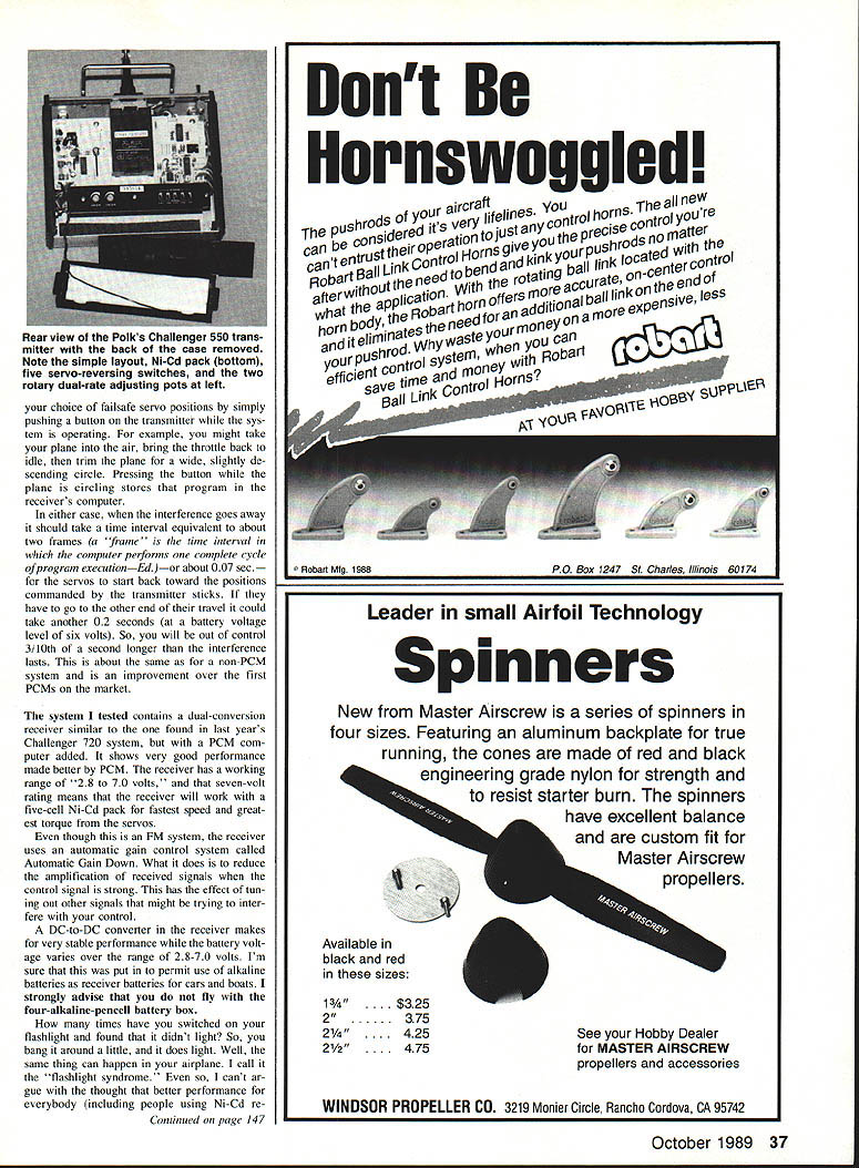
- A slim "S" plug (not compatible with last year's Molex) is used in 1989 aircraft radio gear.
- The HS-422 servo projects its horn less below the mounting plane than the HS-402, uses a custom chip, features a new motor and a very smooth gear train, is faster, and can operate down to 2.8 volts. The output shaft is supported by two-piece metal bearings above and below the final gear to avoid the old plastic-wearing problems.
- All HS-XXX servos are pulse-width controlled and have a 1.55-millisecond neutral, so practically any servo should work with this radio. These servos work well on five-cell Ni-Cd packs, providing more torque and faster operation.
- With minor modification to the plastic plugs, I could use an Airtronics servo in the Challenger 550 receiver. Depending on wire sequence (+, -, signal) other manufacturers' servos may also be compatible.
Bench Tests and Resolution
- I counted 108 steps in the servo responding ±30° to a full swing of the aileron stick in High Rate (reduced by the dual-rate lever), and 31 steps across the full range of the trim bar lever; this count is not affected by the dual-rate switch. This resolution is a function of the PCM computer, which appears to use eight-bit words.
- With a ±30° servo throw, one step corresponds to roughly 0.5° of motion. Re-centering after moving the stick to opposite sides was usually exact and never worse than ±0.5°, which corresponds to one count in the PCM code.
- Using a variable-speed motor-driven device to exercise the landing-gear switch back and forth and watching the point where the servo could no longer keep up, I determined the system can follow 120 cycles per minute with the four-cell Ni-Cd receiver pack. The servo alone can keep up with 140 cycles per minute on 60° travel, which is better than most servos on the market; the system is fast enough for most users.
Miscellaneous
- The servos' resolution and centering are good.
- The frequency flag supplied by Polk's is also nice.
Conclusion
The Challenger 550 PCM system represents a significant step toward consumer adoption of PCM technology: improved interference resistance, programmable failsafe/hold behavior, flexibility in power options, and solid servo resolution and speed. Polk's continues to refine receiver robustness and battery-trip settings to improve safety for Ni-Cd users.
Transcribed from original scans by AI. Minor OCR errors may remain.

