
Radio Technique
George M. Myers
Picking A Propeller
SAY, DAD, what size propeller do I use on this engine? This 12 x 5 that I found in the field kit seems to pull a lot better than the 9 x 7 that you gave me! This, coming from my 13-year-old son, Timothy (AMA 61366) led me to consider the fact that there really isn't very much information around to help you select the best propeller from among the dozens offered by the merchants. Therefore, I will demonstrate a simplified procedure for making the choice. Bear in mind that the propeller must connect the engine to the airplane, aerodynamically speaking, and that both are variable quantities. The engine is subject to wear, changes in fuel and air properties, the effects of various add-on devices like mufflers, air cleaners, spinners, etc., and to the propeller used on it, while the airplane is affected by shape factors, weight, atmospheric changes and the pilot's skill. It is easy to understand why any propeller taken "right out of the box" will only be approximately correct for your situation.
In order to match a propeller to your particular engine setup, you may find that the first problem to be solved is one of shaft diameter. Prop manufacturers drill the hub with a diameter that indicates the size that they had in mind when they made the prop. In general, this keeps you from using a propeller intended for use on an .049 on something completely ridiculous, like a .40. But the engine manufacturers complicate your life by using stepped shaft diameters, foreign (metric) sizes, and so forth. The best answer to this problem that I have found is the stepped reamer made by Fox Manufacturing Co., 5305 Towson, Fort Smith, AR 72901, part no. 70201. Using it, one can fit propellers to any size engine larger than a .15.
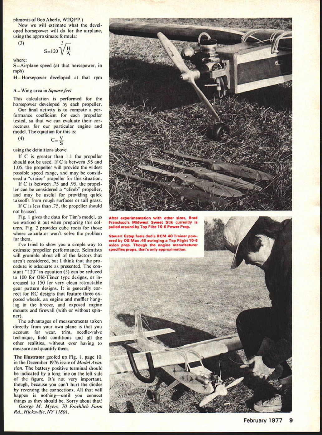
Tim and I poked around our workshop and found 24 propellers that might fit the shaft on his engine, from which I selected 10 that we would test. Tim's engine is a K & B .40 FR, fitted with a Semco .29-.40 closed-end muffler and a Perry air cleaner. The engine is mounted horizontally in a Kraft KM-40 mount (drilled and tapped for #6-32 machine screws, to avoid mount breakage that sometimes occurs when the sheet-metal screws supplied with the mount are used). The mount is screwed to the front of his RCM 15-500, and muffler pressure is used on Duke's fuel. This description is necessary to set the conditions which the propeller must satisfy. We live and fly at sea level in New York.
We took the propellers, the model, our field kit and our Heath Thumb-Tac out in the yard for some tests. Each propeller was fitted to the engine in turn and run until temperatures stabilized, the needle valve was adjusted for maximum rpm, which was recorded. Propeller flying speed at 85% efficiency (nothing is 100% efficient) was calculated, using the equation:
(1) V = PR / 1250
where: V = Speed (in mph) that the propeller will advance through the air at 85% efficiency P = Propeller pitch in inches. The second number on the propeller, usually given as 9 x 7, or 9/7, where 9 is the diameter and 7 is the pitch R = RPM measured by the tachometer
Now we have to know how much horsepower the engine is putting through the propeller. We can measure the torque (twisting force) applied to the fuselage by the engine and use the formula:
(2) H = TR / 33,000
where: T = Torque, measured in foot-pounds R = RPM
This requires some kind of pivoted cradle for the airplane, and a scale for measuring the force generated at some point along the left wing. If the point is about 10 inches from the fuselage centerline, a postage-type scale will do. Friction in the setup, gusts of wind, unbalance of the model and the spiral motion of the air leaving the prop all complicate your life. For our purposes there is an easier way. Obtain one of Peter G. F. Chinn's fine engine reviews published in Model Airplane News covering your engine. Read horsepower versus rpm from the curve. A summary listing of the reviews was given in the August 1975 issue, beginning on page 6. Now we will estimate what the developed horsepower will do for the airplane, using the approximate formula:
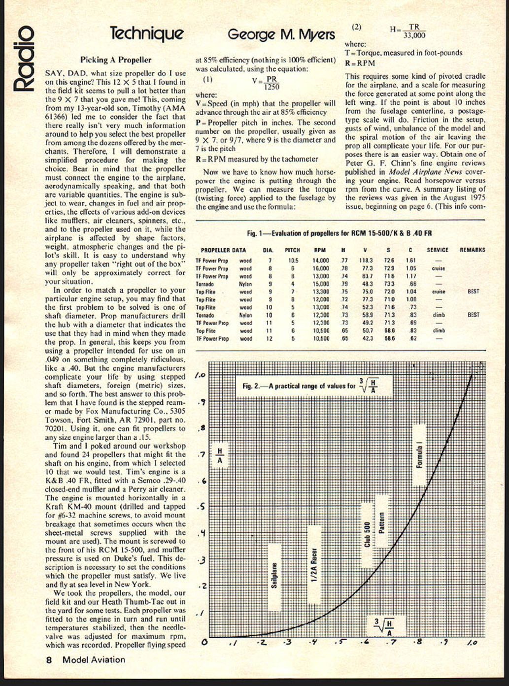
(3) S = 120 (H/A)^(1/3)
where: S = Airplane speed (at that horsepower, in mph) H = Horsepower developed at that rpm A = Wing area in square feet
This calculation is performed for the horsepower developed by each propeller.
Our final activity is to compute a performance coefficient for each propeller tested, so that we can evaluate their correctness for our particular engine and model. The equation for this is:
(4) C = V / S
using the definitions above.
If C is greater than 1.1, the propeller should not be used. If C is between .95 and 1.05, the propeller will provide the widest possible speed range, and may be considered a "cruise" propeller for this situation.
If C is between .75 and .95, the propeller can be considered a "climb" propeller, and may be useful for providing quick takeoffs from rough surfaces or tall grass.
If C is less than .75, the propeller should not be used.
Fig. 1 gives the data for Tim's model, as we worked it out when preparing this column. Fig. 2 provides cube roots for those whose calculator won't solve the problem for them.
I've tried to show you a simple way to estimate propeller performance. Scientists will grumble about all of the factors that aren't considered, but I think that the procedure is adequate as presented. The constant "120" in equation (3) can be reduced to 100 for Old-Timer type designs, or increased to 150 for very clean retractable-gear pattern designs. It is generally correct for RC designs that feature three exposed wheels, an engine and muffler hanging in the breeze, and exposed engine mounts and firewall (with or without spinner).
The advantages of measurements taken directly from your own plane is that you account for wear, trim, needle-valve technique, field conditions and all the other realities, without ever having to measure and quantify them.
The illustrator goofed up Fig. 1, page 10, in the December 1976 issue of Model Aviation. The battery positive terminal should be indicated by a long line on the left side of the figure. It's not very important, though, because you can't hurt the diodes by reversing the connections. All that will happen is nothing—until you connect things as they should be. Sorry about that!
George M. Myers, 70 Froehlich Farm Rd., Hicksville, NY 11801.
Transcribed from original scans by AI. Minor OCR errors may remain.

