
Radio Technique
George M. Myers 70 Froehlich Farm Rd., Hicksville, NY 11801
Abstract
DVM adapters to read peak voltage and to function as an ESM. Charging voltages; caring for Ni‑Cd batteries — Part 5, questions and answers.
Question 1 — Why does my DVM show a lower voltage from the charger than the final voltage of the charged pack?
THIS TIME I'm going to answer the questions about the care and feeding of Ni‑Cd batteries sent in by several readers. These are the types of questions in the minds of many RC modelers.
The simple answer is that a naked digital voltmeter (DVM) is the wrong tool for this job. A DVM in DC mode is designed to read steady DC voltages (as from batteries). Correct measurement of charger voltages requires a different approach. Two factors must be considered: waveform and settling time.
Waveform
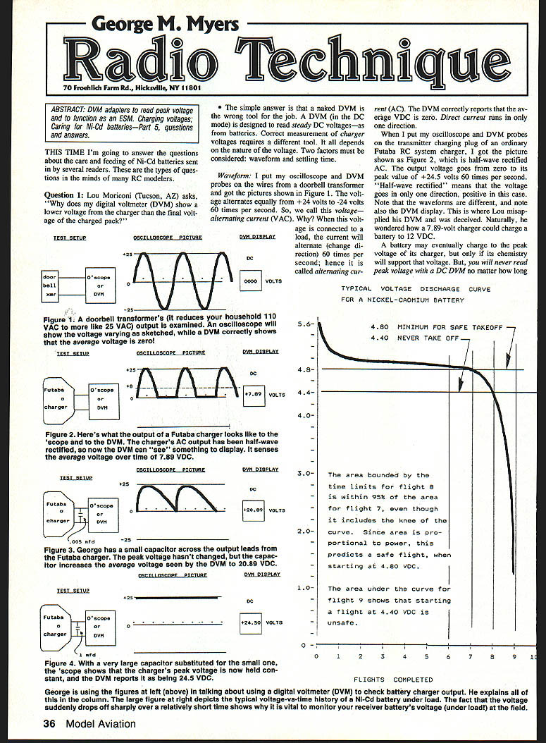
- I put an oscilloscope and DVM probes on the wires from a doorbell transformer and saw a sine wave alternating equally from +24 V to −24 V at 60 Hz — true AC. The DVM correctly reports the average DC voltage as zero.
- On an ordinary Futaba RC-system charger I observed half‑wave‑rectified voltage: the output goes from zero to a peak (about +24.5 V) 60 times per second. This waveform is half‑wave rectified AC (positive only). The DVM reports an average (DC) voltage, not the peak.
- A battery can charge up toward the peak voltage of the charger (if chemistry allows), but a DC DVM will never read the instantaneous peak; it reports an average value over time. That is why Lou saw a seemingly low charger voltage (e.g., 7.89 V reading) even though the charger could charge a battery to a higher DC value.
Using a capacitor to read peak voltage
- Leaving the DVM on the Futaba charger, I placed a 0.005 µF, 600‑V capacitor across the probes. The oscilloscope showed the capacitor charging to peaks and discharging between peaks through the DVM/shunt resistance. The DVM reading rose (for example, to about 20.89 VDC).
- Replacing the 0.005 µF with a 1.0 µF, 600‑V capacitor held the peak voltage almost constant between pulses; the DVM then reported about 24.5 VDC (the charger peak). Increase the capacitance until the DVM reading stops increasing — that gives a practical measurement of peak voltage.
- Practical points:
- The capacitor's voltage rating must exceed the voltage being measured.
- When finished, discharge the capacitor by shorting the terminals (use an insulated tool) — otherwise it can give you a nasty surprise.
This is why a charger that appears to read 7.89 VAC on a DVM can charge a 12‑VDC battery: the charger peak is higher than the DVM's averaged reading.
Settling time
- DVMs have a finite settling time. In DC mode, touching probes to a battery shows the displayed numbers counting up from zero and taking several seconds (commonly ~5 s) to settle. This delay is the instrument's settling time, not an actual change in battery voltage.
- Because of the slow settling time, a DVM cannot follow rapid pulse changes of rectified AC and will report a time‑averaged value.
- Analog (d'Arsonval‑type) meters settle more quickly but respond the same way when a shunt capacitor is used.
Remember: charger peak voltage can be quite a bit larger than the steady terminal voltage of a charged battery. If unsure, use the right instrumentation and techniques.
Question 2 — What is the maximum voltage you can apply to a cell when charging it?
The maximum permissible voltage is determined by the maximum permissible charging current and the total resistance in the charging circuit. Voltage alone is not the sole determinant.
Charger types
I’ll use the following labels:
- Type 1 — Constant‑voltage charger: low internal resistance; terminal voltage stays essentially constant regardless of the number of cells. The charging current equals (charger voltage − battery instantaneous voltage) divided by circuit resistance. These can deliver a wide range of currents (depending on pack state) and can deliver a high initial surge if the battery is deeply discharged.
- Type 2 — Constant‑current charger: delivers essentially the same current whether batteries are discharged or nearly charged. Many RC chargers, when used as intended, behave like Type 2 chargers (overnight rates).
Example (Type 1 behavior):
- Suppose a 6.0‑V constant‑voltage charger is connected to a four‑cell Ni‑Cd pack that is at 4.0 V. The charging voltage available is 6.0 − 4.0 = 2.0 V.
- If total circuit resistance is ~0.5 ohm, the initial charging current is 2.0 ÷ 0.5 = 4 A.
- If the pack were at 0 V, initial current would be 6.0 ÷ 0.5 = 12 A — potentially damaging to small cells.
When a pack reaches the charger's terminal voltage (6 V in this example), charging current falls to zero; thus a constant‑voltage charger can be designed to avoid overcharging in normal use, but initial surges can be large.
Practical advice
- Batteries nearly at 0 V should be recharged first on a Type 2 (constant‑current) charger for about 24 hours to avoid damage from a large initial surge of a Type 1 charger.
- Voltage rating of the charger is not the only variable — current and circuit resistance matter.
Observations on a real Futaba charger
- Typical RC system chargers often have two pairs of leads: one for the airborne (flight) battery and one for the transmitter battery; plugs differ to avoid mistakes. The Futaba charger I checked had peak voltages of about 16.8 V and 24.5 V on the two outputs and normally delivered about 65 mA to each connected battery lead.
- Reversing plug connections produced different currents (e.g., one lead produced 25 mA when connected to the flight battery, the other produced 220 mA when used on the flight battery), indicating the charger was not an ideal Type 2 but was designed to support various pack sizes.
- The Futaba engineer evidently provided voltages to support 8‑ or 9‑cell transmitter packs and 4‑ or 5‑cell receiver packs; the charger delivers roughly 50–65 mA to those packs and can be used as an overnight charger for them.
If you don’t know exactly what your charger is doing, follow the manufacturer's instructions. If you must experiment, understand your instruments and use correct measurement techniques. Test on purpose.
Question 3 — What is a safe minimum voltage to start a flight?
This is like asking how much fuel should be in the tank. Voltage by itself is a poor indicator of remaining charge because terminal voltage drops with increasing load even though remaining charge may be unchanged. Still, because DVMs are cheap and common, you can adapt one to get a useful field check.
Convert a DVM into a simple ESM (expanded‑scale meter)
Build a simple loaded test that simulates a modest load:
- Buy two 10‑ohm, 10‑W wirewound resistors.
- Put them side‑by‑side and twist their leads on each end together (they are then in parallel to form ~5 ohms).
- Solder these resistor pairs across a charging plug (matching your system plug). Connect the DVM in parallel with the resistor assembly.
- When plugged into your plane's charging jack, the resistors draw about 1 A; the DVM will show an initial voltage and then it will fall over ~30 seconds to a stable value. This simulates a moderate in‑air load (similar to two servos moving).
Interpretation:
- For a four‑cell Ni‑Cd pack, if the value after 30 seconds is 4.80 V or more, you probably have enough charge left for another 10‑minute flight.
- For a five‑cell pack, look for about 6.00 V or more.
- The test draws about 10 mAh while running and dissipates about 5 W; resistors may become warm.
- Be conservative — instrument tolerances and pack variability mean you should err on the safe side.
End‑of‑charge standards and practical flying limits
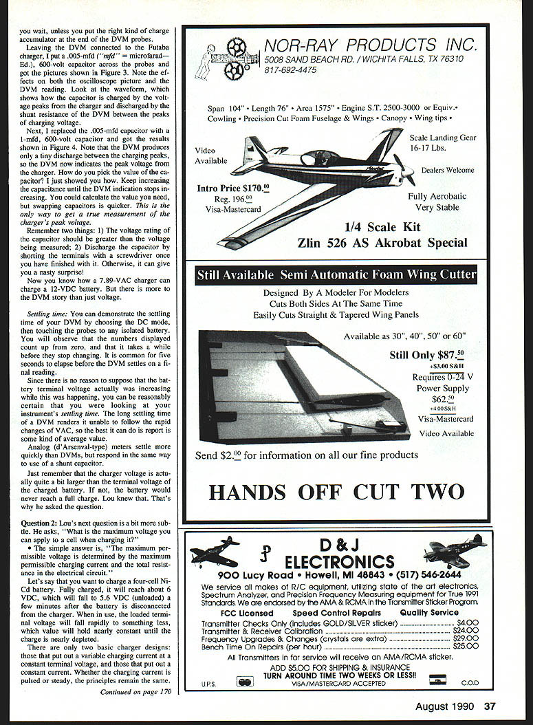
- The ANSI standard for end‑of‑charge voltage for a Ni‑Cd cell is about 0.9 V under load; in practice this usually corresponds to about 1.1 V per cell without load for RC hobby use.
- At 1.1 V per cell (4.4 V under load for a four‑cell pack), the pack has very little energy left and it is never safe to start a flight. If you avoid discharging below ~4.4 V under load you will avoid cell‑reversal failures.
- The flat part of the discharge curve for an average four‑cell 550‑mAh pack under typical load ends at about 4.8 V; when the pack is still on that flat portion there is usually enough energy for one more ~10‑minute flight.
- Because batteries vary, it's better to test packs on the ground (measure how long a full pack actually lasts) and then use time limits in flight. Example: if a fully charged pack gives two hours of service, stop flying at ~1.5 hours or change packs.
Alternatives and safety measures
- Use larger batteries, a field charger/cycler (e.g., CaRa Automatic Cycler‑Charger, Polk's Multi‑Charge‑A‑Matic), or redundancy such as a failsafe device to avoid getting the last possible bit of energy from packs in flight.
- Follow good practices: know your equipment, test on the ground, and be conservative in the air.
---
Get the right answers on purpose.
Transcribed from original scans by AI. Minor OCR errors may remain.

