
Radio Technique
George M. Myers
EVERY SO OFTEN I feel inclined to pass along some simple little electronic gadgets that are fun to build and use, so this column is for the guys with the hot soldering irons and snappy side-cutters.
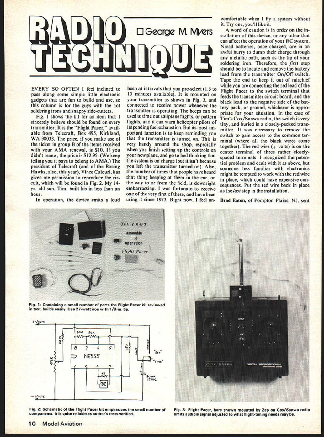
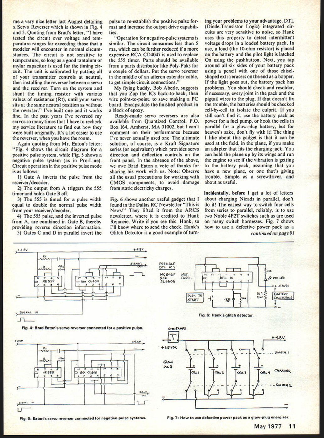
Fig. 1 shows the kit for an item that I sincerely believe should be found on every transmitter. It is the "Flight Pacer," available from Telecraft, Box 495, Kirkland, WA 98033. The price, if you make use of the ticket in group B of the items received with your AMA renewal, is $10. If you didn't renew, the price is $12.95. (We keep telling you it pays to belong to AMA.) The president of Telecraft (and of the Boeing Hawks, also, this year), Vince Calouri, has given me permission to reproduce the circuit, which will be found in Fig. 2. My 14-yr. old son, Tim, built his in less than an hour.
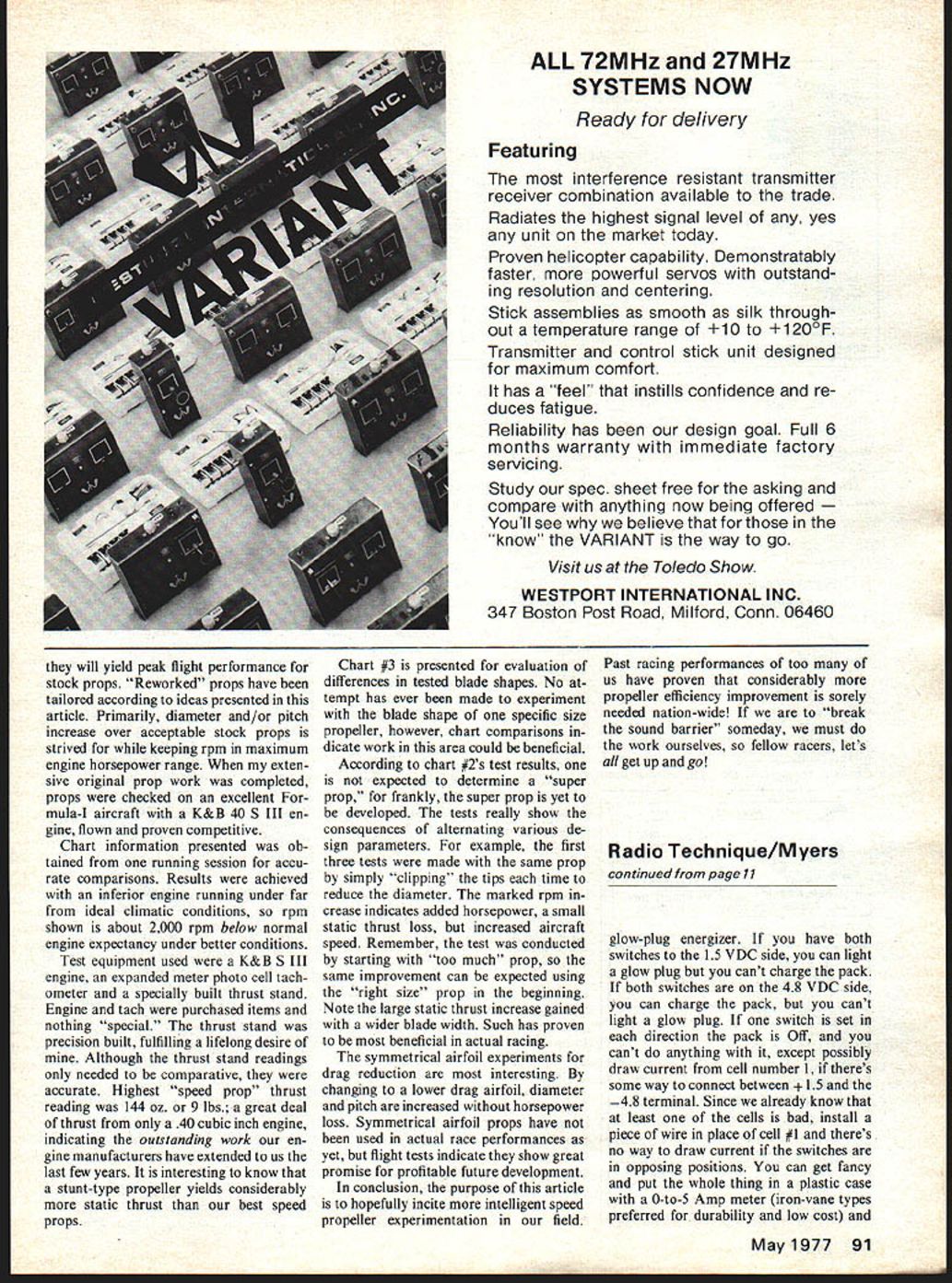
In operation, the device emits a loud beep at intervals that you pre-select (1.5 to 10 minutes available). It is mounted on your transmitter as shown in Fig. 3, and connected to receive power whenever the transmitter is operating. The beeps can be used to time out sailplane flights, or pattern flights, and it can warn helicopter pilots of impending fuel exhaustion. But its most important function is to keep reminding you that the transmitter is turned on. This is very handy around the shop, especially when you finish setting up the controls on your new plane, and go to bed thinking that the system is on charge (but it isn't because you left the transmitter turned on). Also, the number of times that people have heard that thing beeping at them in the car, on the way to or from the field, is downright embarrassing. I was fortunate to receive one of the very first of these, and have been using it since 1973. Right now, I feel uncomfortable when I fly a system without it. Try one, you'll like it.
A word of caution is in order on the installation of this device, or any other that can affect the operation of your RC system. Nicad batteries, once charged, are in an awful hurry to dump their charge through any metallic path, such as the tip of your soldering iron. Therefore, the first step should be to locate and remove the battery lead from the transmitter On/Off switch. Tape the end to keep it out of mischief while you are connecting the red lead of the Flight Pacer to the switch terminal that feeds the transmitter circuit board, and the black lead to the negative side of the battery pack, or ground, whichever is appropriate for your situation. In the case of Tim's Cox/Sanwa radio, the switch is very tiny, and buried in a closely-packed transmitter. It was necessary to remove the switch to gain access to the common terminal (where all the black wires come together). The red wire (+ volts) is on the center terminal of three rather closely-spaced terminals. I recognized the potential problem and dealt with it as above, but someone less familiar with electronics might be tempted to work with the red wire in place, which could have expensive consequences. Put the red wire back in place as the last step in the installation.
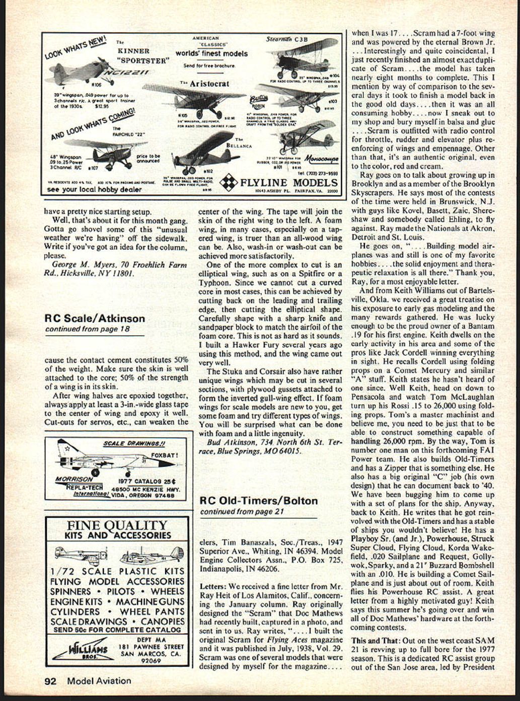
Brad Eaton, of Pompton Plains, N.J., sent a nice letter last August detailing the Servo Reverser shown in Fig. 4 and 5. Quoting Brad's letter: "I have tested the circuit over voltage and temperature ranges far exceeding what a modeler will encounter under normal circumstances. The circuit is sensitive to temperature, so a long-life tantalum/mylar capacitor is used in the timing circuit. The unit is calibrated by putting the transmitter controls at neutral, installing the reverser between the servo and receiver, then shunting the timing resistor with various values of resistance R_t until the servo sits at the same neutral position with the reverser. I've built it and it has worked fine for years. I've reversed servos many times and have rechecked the service literature to find out how it was built originally. It's a lot easier to use a reverser if you have the room."
Again quoting Mr. Eaton's letter: Fig. 4 shows the circuit diagram for the positive-pulse system; Fig. 5 shows the negative-pulse system.
Pro-Line circuit operation (positive pulse mode) follows:
- Gate A inverts the pulse from the receiver/decoder.
- The output triggers the 555 timer which holds Gate B off.
- The 555 timed pulse width equals double the normal pulse width from the receiver/decoder.
- The 555 pulse, inverted, and the pulse combined at Gate B thereby provides reverse direction information.
- Gates C and D, in parallel, invert the pulse to re-establish a positive pulse that increases output drive capabilities.
Operation of negative-pulse systems is similar. The circuit consumes less than 5 mA and can be further reduced by using the RCA CD4047 in place of the 555 timer. Parts should be available from parts distributors like Poly-Paks for a couple of dollars. Put the servo reverser in the middle of an aileron extender cable to get simple circuit connections, as flying buddy Bob Aberle suggested. My flying buddy, Bob Aberle, suggests that you zap the ICs back-to-back, then wire point-to-point, to save making a PC board. Encapsulate the finished product in a block of epoxy.
Ready-made servo reversers are also available from Quantized Control, P.O. Box 164, Amherst, MA 01002, but I can't comment on their performance because I've never actually used one. The ultimate solution, of course, is a Kraft Signature series (or equivalent) which provides servo direction and deflection controls on the front panel. In the absence of the above, we owe Brad Eaton a vote of thanks for sharing his work with us. Note: Observe all the usual precautions for working with CMOS components, to avoid damage from static electricity charges.
Fig. 6 shows another useful gadget that I found in the Dallas RC Newsletter "This is News!" They lifted it from the ARCS newsletter, where it is credited to Hank Rejneuec. Write if you see this, Hank, so I'll know where to send the check. Hank's Glitch Detector is a good example of turning your problems to your advantage. DTL (Diode-Transistor Logic) integrated circuits are very sensitive to noise, so Hank uses this property to detect intermittent voltage drops in a loaded battery pack. In use, a load (the 10-ohm resistor) is placed on the battery and the pilot light is latched on using the pushbutton. Next, put tape around all six sides of your battery pack using a pencil with one of those chisel-shaped extra erasers on the end as a bopper. If the light goes out, the battery pack has problems. You should check and resolder, if necessary, every joint in the pack and the pigtail wires to the plug. If that doesn't fix the trouble, the batteries should be checked cell-by-cell to isolate the culprit. If you still can't find it, use the battery pack as power for a fuel pump, or hook the cells in parallel for a glow-plug battery, but for heaven's sake, don't fly with it! The thing I like about this gadget is that it can be used at the field, in the plane, if you make an adapter that fits the charging jack. You can hold the plane up by its wings and run the engine to see if the vibration is getting to the battery pack, assuming that you have a new plane, or one that's giving trouble. Simple as a screwdriver, and about as useful.
Incidentally, before I get a lot of letters about charging Nicads in parallel, don't do it! The easiest way to switch four cells from series to parallel, reliably, is to use two Noble 4P2T switches such as are used on many switch harnesses. Fig. 7 shows how to use a defective power pack as a glow-plug energizer. If you have both switches to the 1.5 VDC side, you can light a glow plug but you can't charge the pack. If both switches are on the 4.8 VDC side, you can charge the pack, but you can't light a glow plug. If one switch is set in each direction the pack is Off, and you can't do anything with it, except possibly draw current from cell number 1, if there's some way to connect between +1.5 and the -4.8 terminal. Since we already know that at least one of the cells is bad, install a piece of wire in place of cell #1 and there's no way to draw current if the switches are in opposing positions. You can get fancy and put the whole thing in a plastic case with a 0-to-5 Amp meter (iron-vane types preferred for durability and low cost) and have a pretty nice starting setup.
Well, that's about it for this month gang. Gotta go shovel some of this "unusual weather we're having" off the sidewalk. Write if you've got an idea for the column, please.
George M. Myers, 70 Froehlich Farm Rd., Hicksville, NY 11801.
Transcribed from original scans by AI. Minor OCR errors may remain.

