
Radio Technique
George M. Myers
ABSOLUTE RADIATED power measurements are extremely difficult to make, therefore rarely done. Most often a person who wishes to know something about his transmitter performance will connect it to a "standard dipole," then turn it on and measure the energy received in the vicinity of the antenna, using a field-strength meter. Next, he will repeat the measurements, this time with the transmitter connected to whatever antenna he proposes to use it with. The results are then reported as "—Db, relative to a standard dipole."
These measurements are not easy to make, because they are affected by such extraneous factors as reflections from metal objects in the vicinity, conduction of the radiated signal by buried and suspended wires (like electric power cables) and the radiation from other transmitters in the vicinity. The term "other transmitters" includes radiation from local oscillators in receivers, like TV, CB, car radios, etc. The problems enumerated are further complicated by considerations of the relative sizes and alignments of the transmitter and field-strength meter antenna, and their spacing relative to the wavelength of the transmitted signal.
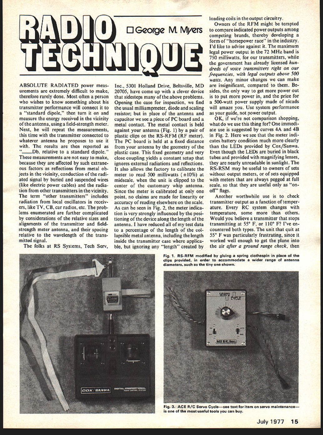
The folks at RS Systems, Tech Serv, Inc., 5301 Holland Drive, Beltsville, MD 20705, have come up with a clever device that sidesteps many of the above problems. Opening the case for inspection, we find the usual milliammeter, diode and scaling resistor; but in place of the antenna and capacitor we see a piece of PC board and a metal contact. The metal contact is held against your antenna (Fig. 1) by a pair of plastic clips on the RS-RFM (RF meter). The PC board is held at a fixed distance from your antenna by the geometry of the plastic case. This fixed geometry and very close coupling yields a constant setup that ignores external radiations and reflections. It also allows the factory to calibrate the meter to read 500 milliwatts (±10%) at midscale, when the unit is clipped to the center of the customary whip antenna. Since the meter is calibrated at only one point, no claims are made for linearity or accuracy of reading elsewhere on the scale.
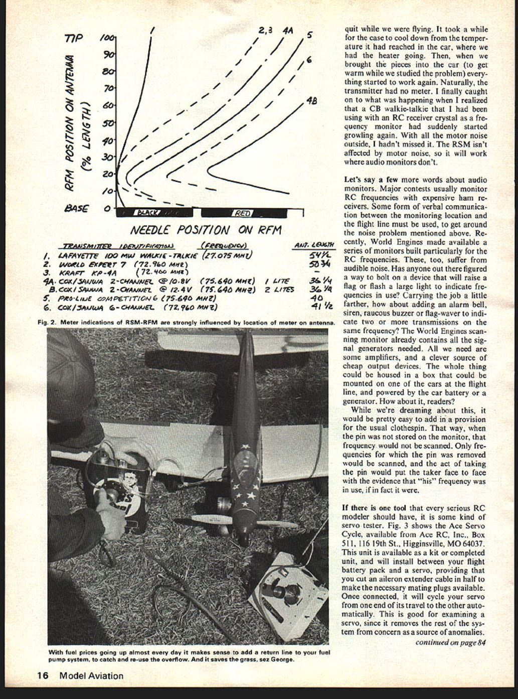
As can be seen in Fig. 2, the meter indication is very strongly influenced by the positioning of the device along the length of the antenna. I have reduced all of my test data to a percentage of the length of the collapsible metal antenna, including the length inside the transmitter case where applicable, but ignoring any "length" created by loading coils in the output circuitry.
Owners of the RFM might be tempted to compare indicated power outputs among competing brands, thereby developing a form of "horsepower race" in the industry. I'd like to advise against it. The maximum legal power output in the 72 MHz band is 750 milliwatts, for our transmitters, while the government has already licensed hundreds of voice transmitters right on our frequencies, with legal outputs above 500 watts. Any minor changes we can make are insignificant, compared to them. Besides, the only way to get more power out is to put more power in, and the price for a 500-watt power supply made of nicads will amaze you. Use system performance as your guide, not power output.
OK, if we're not comparison shopping, what do we use this thing for? One immediate use is suggested by curves 4A and 4B in Fig. 2. Here we see that the meter indicates battery condition much more clearly than the LEDs provided by Cox/Sanwa. Even though the LEDs are buried in black tubes and provided with magnifying lenses, they are nearly unreadable in sunlight. The RS-RSM may be useful to owners of sets without output meters, or of sets equipped with meters that are always pegged at full scale, so that they are useful only as "on-off" flags.
Another worthwhile use is to check transmitter output as a function of temperature. Every RC system changes with temperature, some more than others. Would you believe a transmitter that stops transmitting at 55°F, or 110°F? I've encountered both types. The unit that quit at 55°F was particularly frustrating, since it worked well enough to get the plane into the air after a ground range check, then quit. I took the case off, let it cool down, and when the temperature reached that of the car heater I was using to warm it, the unit started to work again. Naturally the transmitter had no meter, so I finally caught what was happening and realized that a CB walkie-talkie using an RC receiver crystal frequency monitor suddenly started growling again. Motor noise outside had caused the problem I hadn't missed. The RSM isn't affected by motor noise and will work where audio monitors don't.
Let's say a few words about audio monitors. Major contests usually monitor RC frequencies with expensive ham receivers. Some form of verbal communication between the monitoring location and the flight line must be used to get around the noise problem mentioned above. Recently World Engines made available a series of monitors built particularly for the RC frequencies. These, too, suffer from audible noise. Has anyone out there figured a way to bolt on a device that will raise a flag or flash a large light to indicate frequencies in use? Carrying the job a little farther, how about adding an alarm bell, siren, raucous buzzer or flag-waver to indicate two or more transmissions on the same frequency? The World Engines scanning monitor already contains all the signal generators needed. All we need are some amplifiers, and a clever source of cheap output devices. The whole thing could be housed in a box that could be mounted on one of the cars at the flight line, and powered by the car battery or a generator. How about it, readers?
While we're dreaming about this, it would be pretty easy to add in a provision for the usual clothespin. That way, when the pin was not stored on the monitor, that frequency would not be scanned. Only frequencies for which the pin was removed would be scanned, and the act of taking the pin would put the taker face to face with the evidence that "his" frequency was in use, if in fact it were.
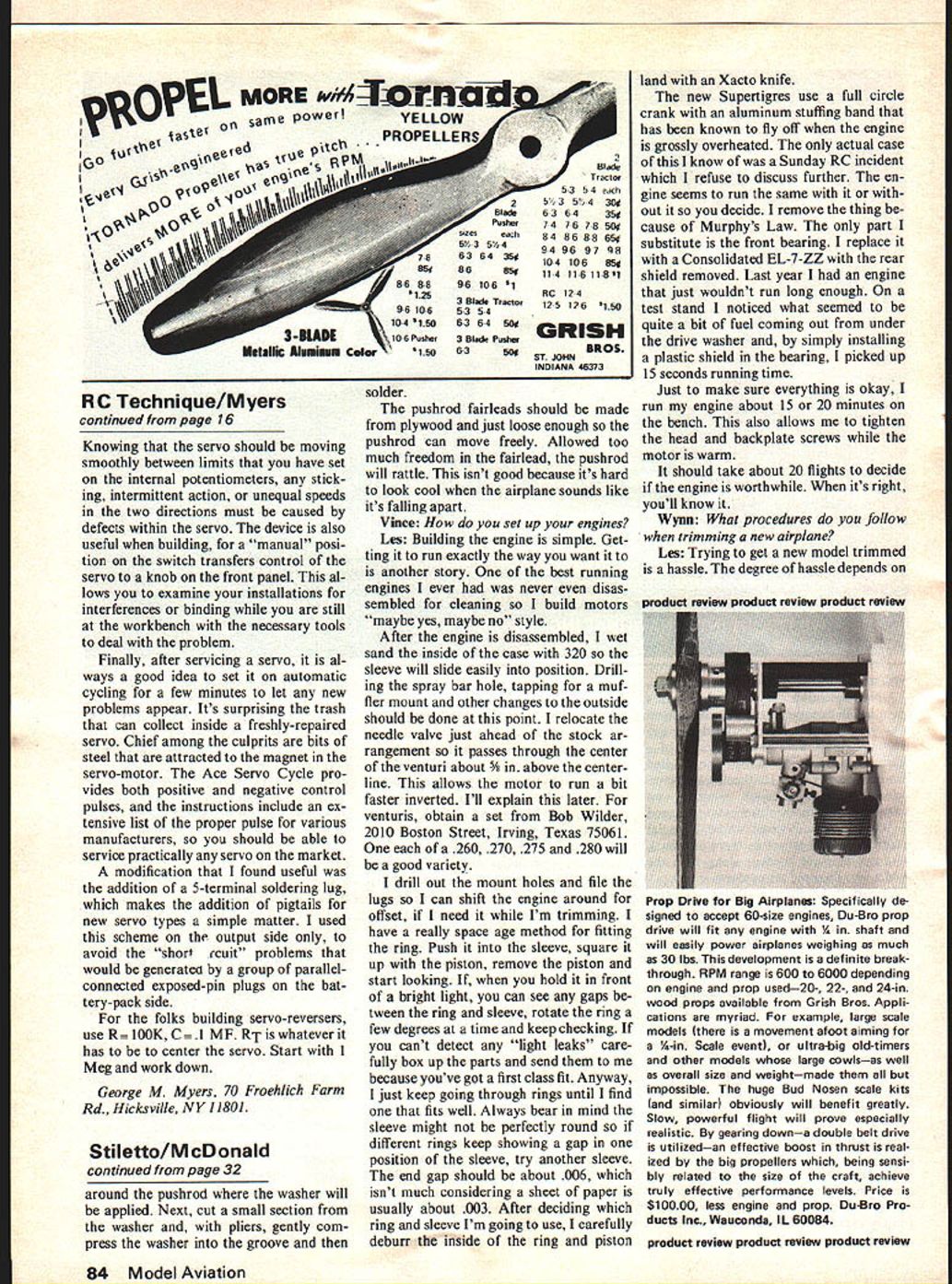
If there is one tool that every serious RC modeler should have, it is some kind of servo tester. Fig. 3 shows the Ace Servo Cycle, available from Ace RC, Inc., Box 511, 116 19th St., Higginsville, MO 64037. This unit is available as a kit or completed unit, and will install between your flight battery pack and a servo, providing that you cut an aileron extender cable in half to make the necessary mating plugs available. Once connected, it will cycle your servo from one end of its travel to the other automatically. This is good for examining a servo, since it removes the rest of the system from concern as a source of anomalies.
RC Technique/Myers
Knowing that the servo should be moving smoothly between limits that you have set on the internal potentiometers, any sticking, intermittent action, or unequal speeds in the two directions must be caused by defects within the servo. The device is also useful when building, for a "manual" position on the switch transfers control of the servo to a knob on the front panel. This allows you to examine your installations for interferences or binding while you are still at the workbench with the necessary tools to deal with the problem.
Finally, after servicing a servo, it is always a good idea to set it on an automatic cycling for a few minutes to let any new problems appear. It's surprising the trash that can collect inside a freshly-repaired servo. Chief among the culprits are bits of steel that are attracted to the magnet in the servo-motor. The Ace Servo Cycle provides both positive and negative control pulses, and the instructions include an extensive list of the proper pulse for various manufacturers, so you should be able to service practically any servo on the market.
A modification that I found useful was the addition of a 5-terminal soldering lug, which makes the addition of pigtails for new servo types a simple matter. I used this scheme on the output side only, to avoid the "short circuit" problems that would be generated by a group of parallel-connected exposed-pin plugs on the battery-pack side.
For the folks building servo-reversers, use R = 100K, C = .1 MF. R/T is whatever it has to be to center the servo. Start with 1 Meg and work down.
George M. Myers, 70 Froehlich Farm Rd., Hicksville, NY 11801.
Transcribed from original scans by AI. Minor OCR errors may remain.

