
Radio Technique
George M. Myers
ROYAL ELECTRONICS is selling the neatest little maintenance trainer I've seen in years. It's disguised under the name V2A, 2-channel receiver, and sells currently for $21.95. What you get for the money is a 2-channel RC receiver kit (easily convertible to 4 channels). It is a simple, straight-forward design with a good construction manual, and is just difficult enough to solder to give you good training on how to solder small parts in tight places. Now, even if you never fly the thing, you will be miles ahead in understanding how to care for your factory-built equipment after you have built this little receiver; particularly if you stick with it until you have corrected your mistakes (if any) and made it work. I can't think of anything else that will teach you as much for the price.
My son, Tim, is the chief kit builder for evaluating anything that is to be considered for this column. If a normal, interested, junior-high school student (possibly a little brighter than normal) can do it, it's reasonable to suppose that my readers can. Tim succeeded. Now, before you rush off to phone in an order, I'd like to make a suggestion. If you have any plans to fly the receiver, order the 4-channel conversion (P.N. 000436) for an additional $2.95. The reasons are as follows:
- If you ever expect to piggy-back the ICs as required, the time to do it is before installing IC #1. I can't imagine anyone adding IC #2 after the kit is completed; there's no room for the tip of the soldering iron.
- The servo pulses from your transmitter may not put elevator and aileron on the same stick if you can't select from at least four pulses.
Let me illustrate what I mean by comment 2. Saturday, a family showed up at the field with a nicely-built model and a Cox/Sanwa 2-channel radio. As absolute beginners, they wanted someone to fly it for them. Unfortunately, no one in the club flies Mode I (elevator on the left stick), and I had just enough experience with my Shoestring to know that I didn't want the responsibility, either. What to do? As it turned out, their system was on the same frequency as my son's Cox/Sanwa 6-channel, so I suggested that we might as well give it a try. As it turned out, Tim's Mode 2 transmitter operated their system, but his throttle stick worked their rudder and his aileron worked their elevator. No good! Sorry, folks. They couldn't get the engine to run, so they went home to find out why. Disappointment.
The only option left to us at that point would have been to transfer Tim's receiver, but the engine troubles made that unnecessary. Now, the reason we were stopped was that the first two pulses in Tim's control stream did not come from the aileron/elevator control stick. Even if they had, we might have found the controls reversed, which would have meant exchanging plugs in the servo receptacles in the receiver. It's also possible that the servo direction would have reversed, making necessary a move of the pushrod to the opposite side of the servo arm.
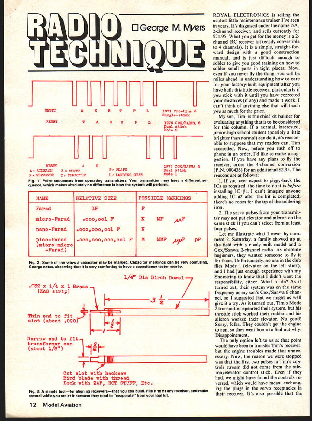
Last month I discussed control pulses; you may remember I said the transmitter encoder interrogates control-stick potentiometers sequentially in order to create On-Off commands for the transmitter oscillator. What sequence does it use? That's up to the person who wires the transmitter — he could do it in a random manner and the system would still work normally. The only difference you would notice is that you would have to plug servos into different receptacles in the receiver than you might otherwise expect to find. Fig. 1 shows some pulse sequences measured on transmitters; shop names are applied to pulse sequences due to the conventional way of assigning functions to control sticks. After all, a fellow who purchases a car might decide to name controls Accelerate, Brake, Shift, Clutch, Steering, Lights. The point I'm trying to make is that airplane RC systems based on a 4-channel setup can expect to find aileron and elevator somewhere among pulses 1 through 4. Additional functions will be assigned pulses 5 through 8. Therefore building a 4-channel receiver right from the start assures success.
Getting back to the Royal receiver kit. You may not know anything at all about electronics except which end of the soldering iron gets hot, but if you can read English and follow instructions you can build this successfully. The only trouble you might have is understanding the markings on the capacitors. Therefore, we will now enter a brief discussion of that subject.
Electrical capacitance is measured in units called Farads, after a famous British scientist, Michael Faraday (1791-1867) who is credited with discovery of electromagnetic induction, which is what makes this hobby possible. We owe a lot to Mr. Faraday, and you may notice that he died only 110 years ago. This is a young hobby!
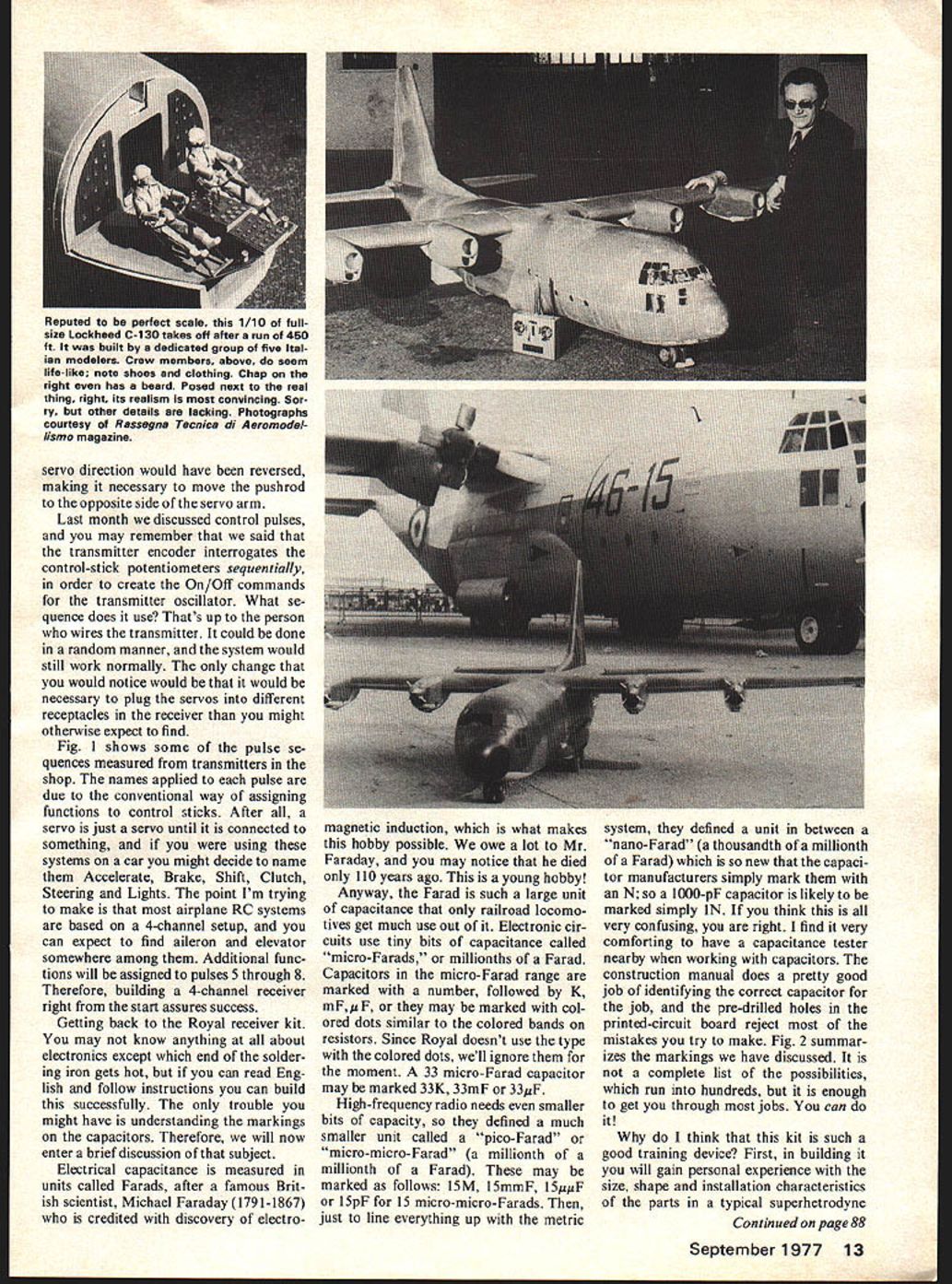
Anyway, the Farad is such a large unit of capacitance that only railroad locomotives get much use out of it. Electronic circuits use tiny bits of capacitance called "micro-Farads," or millionths of a Farad. Capacitors in the micro-Farad range are marked with a number, followed by K, mF, μF, or they may be marked with colored dots similar to the colored bands on resistors. Since Royal doesn't use the type with the colored dots, we'll ignore them for the moment. A 33 micro-Farad capacitor may be marked 33K, 33mF or 33μF.
High-frequency radio needs even smaller bits of capacity, so they defined a much smaller unit called a "pico-Farad" or "micro-micro-Farad" (a millionth of a millionth of a Farad). These may be marked as follows: 15M, 15mmF, 15μμF or 15pF for 15 micro-micro-Farads. Then, just to line everything up with the metric system, they defined a unit in between — a "nano-Farad" (a thousandth of a millionth of a Farad) which is so new that the capacitor manufacturers simply mark them with an N; so a 1000-pF capacitor is likely to be marked simply 1N. If you think this is all very confusing, you are right. I find it very comforting to have a capacitance tester nearby when working with capacitors. The construction manual does a pretty good job of identifying the correct capacitor for the job, and the pre-drilled holes in the printed-circuit board reject most of the mistakes you try to make. Fig. 2 summarizes the markings we have discussed. It is not a complete list of the possibilities, which run into hundreds, but it is enough to get you through most jobs. You can do it!
Why do I think that this kit is such a good training device? First, in building it you will gain personal experience with the size, shape and installation characteristics of the parts in a typical superheterodyne
Radio Technique
receiver. If you will read every word and study every drawing in the construction manual, and ask questions when you don't understand, you will obtain a fine basic introduction to electronics. If you follow all of the instructions correctly, then you will gain practical experience in aligning the receiver to the transmitter. Herein lies the greatest benefit, because most of the jittery sets you will encounter need nothing more than re-alignment to restore like-new performance. Vibration loosens the parts and causes the alignment slugs to move slightly, and age causes some of the components to change value slightly with time, which causes the receiver to drift out of alignment. If you know how to realign your set, you can extend the useful life of your set, and maybe prevent a crash or two.
Finally, if you do something wrong, and persist until you find and fix it, then you will have gained valuable experience in analyzing symptoms (trouble-shooting). All of this can be done free of guilt or fear of failure because "you never really intended to fly it anyway," and that psychological freedom will lead you to perform experiments that you would never dream of doing to your "official" factory-built RC system. It's a great way to learn!
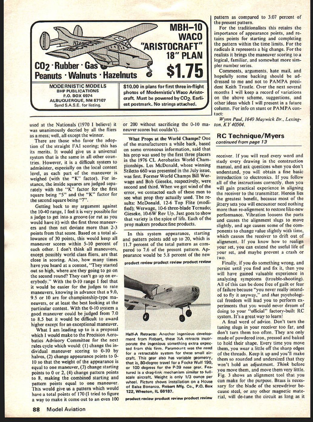
A final word of advice. Don't turn the tuning slugs in your receiver too far, and don't turn them too often. They are only made of powdered iron, pressed and baked to hold their shape. Every time you move them, you wear a little of the sharp edges of the threads. Keep it up and you'll make them so rounded and undersized that they won't hold an adjustment. Think before you move them, and move them very little. Fig. 3 shows an alignment tool that you can make for the purpose. Brass is necessary for the blade of the screwdriver because steel, or any other magnetic material, will de-tune the circuit as long as it is in the vicinity of the slug. Royal Electronics is selling the neatest little maintenance trainer I've seen in years. It's disguised under the name "2-channel receiver" and sells currently for $21.95. What you get for your money is a 2-channel R/C receiver kit, easily convertible to 4 channels — a simple, straightforward design, good construction, and a manual just difficult enough to solder to give good training in soldering small parts in tight places. Now, even if you never fly the thing, you'll be miles ahead in understanding the care of factory-built equipment after you have built a little receiver, particularly a stick, and have corrected mistakes made in the work. I can't think of anything else that will teach so much. My son Tim, chief kit builder and evaluator, considers it suitable for the sort of reader this column normally interests — a junior-high school student, possibly a little brighter than normal. Tim succeeded.
Now, before you rush off to phone order, I'd like to make a suggestion: if you have plans to fly the receiver, order the 4-channel conversion, P/N 000436 — additional $2.95. The reasons follow.
- If you ever expect to piggy-back, ICs required — I can't imagine anyone installing IC #1 and then, later, adding IC #2 after the kit is completed; there's no room or tip for a soldering iron.
- The servo pulses a transmitter uses may put elevator and aileron on the same stick; you can't select at least four pulses. Let me illustrate what I mean.
One Saturday my family showed up at the field with a nicely-built model and a Cox/Sanwa 2-channel radio. As absolute beginners they wanted someone to fly. Unfortunately, no club member wanted the responsibility. As it turned out, the system was on the same frequency as my son's Cox/Sanwa 6-channel, so we suggested we might give it a try. Tim's Mode 2 transmitter operated the system: throttle worked, rudder worked, aileron worked — but not elevator. No good. We couldn't get the engine to run and went home to find out why. The disappointment left us with the option of transferring Tim's receiver, but engine troubles made that unnecessary.
Now, the reason for the confusion is the first two pulses. Tim's control-stream did not map to the same stick functions we expected. If the aileron/elevator control stick had been reversed, it would have meant exchanging plugs at the servo receptacles on the receiver. It's also possible a servo's direction would have been reversed, making it necessary to move the pushrod to the opposite side of the servo arm.
Last month we discussed control pulses; you may remember I said the transmitter encoder interrogates the control-stick potentiometers sequentially in order to create on/off commands for the transmitter oscillator. What sequence does it use? That's up to the person who wired the transmitter — it could be done in a random manner and the system would still work normally. The only change you would notice would be that it might be necessary to plug servos into different receptacles on the receiver than you might otherwise expect.
Fig. 1 shows some pulse sequences measured in transmitters; the shop names applied to pulses are due to the conventional way of assigning functions to the control sticks. After all, you might just name servos as you please — like in car systems where one might name controls Accelerate, Brake, Shift, Clutch, Steering, Lights. The point I'm trying to make is that in airplane R/C systems based on a 4-channel setup you can expect to find aileron and elevator somewhere among the first four pulses. Additional functions will be assigned pulses 5 through 8. Therefore, building a 4-channel receiver right from the start assures you of the flexibility and compatibility needed to work with the variety of pulse sequencing used in different transmitters.
Transcribed from original scans by AI. Minor OCR errors may remain.

