
Radio Technique . . . George Myers
Introduction
I spent a pleasant lunch hour discussing servo-reversing techniques with Bob Aberle. Bob reviews radios for Flying Models magazine and probably knows what is being offered by the various manufacturers better than any salesman. He also owns the latest equipment, including a Kraft Signature system that he bought last year (partly because I kept urging him to spend his money on it). As a result of this, and other discussions, we came to an agreement that someone has missed the point when servo-reversing methods were sent to market. Do you want the plane adjusted to fit the transmitter, or vice versa? Before showing you what we decided, and why, it would be reasonable to consider how the deed can be done.
What is "servo-reversing"?
"Servo-reversing" is the term we will use to describe any method that can be used to change the direction of motion of a control surface (e.g., the elevator) with respect to a given motion of the control stick on the transmitter. Servo-reversing can be introduced at several points in the link from your hand to the control surface, to wit:
- At the control stick
- Inside the transmitter electronic package
- Inside the receiver electronic package
- Between the receiver and the servo
- Inside the servo electronic package
- At the servo/pushrod interface
- At the control surface
Methods and commentary
Last month we showed you how Hank Prew performed servo-reversing on his MRC772 by removing the stick assembly and reinstalling it rotated 180° from its original position. Many sets can be reversed in this manner and the primary disadvantage of the method is that the location of the trim lever changes. Personally, I find that the variety of trim-lever locations is one of the biggest nuisances I face when teaching others to fly R/C. You have to reach them without looking, and when you need them most (such as the first test flight on someone else's plane) you can't find them. So, while this method is cheap, quick and easy, there has to be a better way.
- At the control stick
It might be possible to cut the leads to your stick potentiometer and install a non-polarized 3-pin plug. Then you can simply reverse the plug to reverse action, but you will have to re-zero the system in some way. If your servo can be re-zeroed by pushing a screwdriver or hex-wrench down the hole left by removing the screw that attaches the output wheel, this might be a good way. For one thing, you will spread the wear on the servo-potentiometer track. But the disadvantage is that you have to open up both the transmitter and the airplane to make the changes. Another way would be to add electrical trim inside the transmitter case.
- Inside the transmitter or receiver electronics
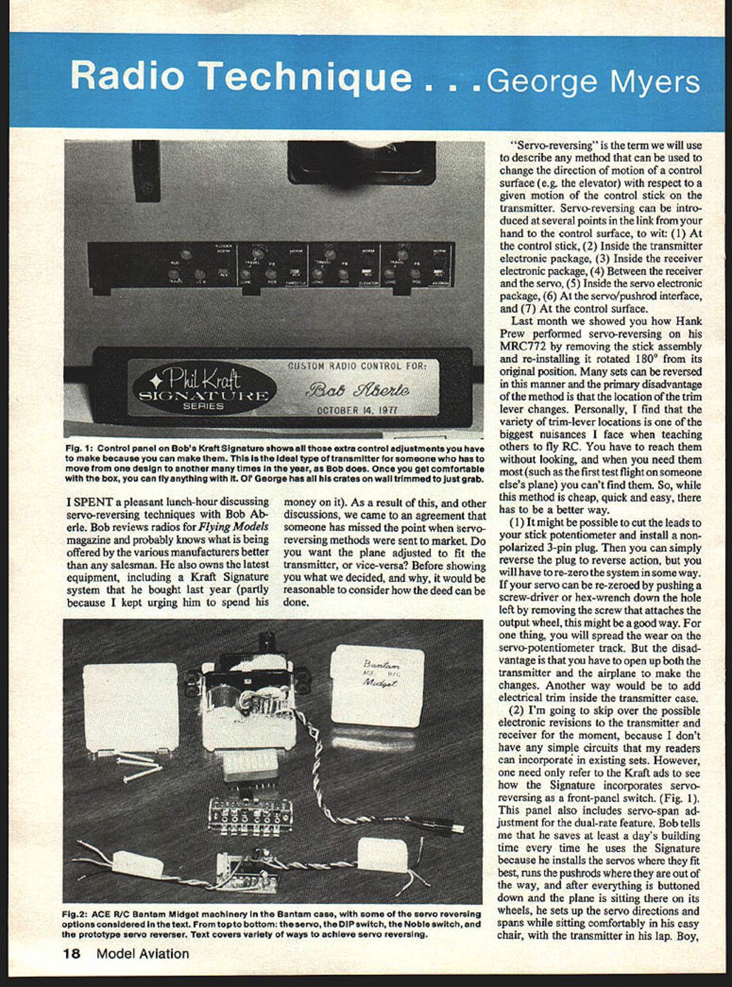
I'm going to skip over the possible electronic revisions to the transmitter and receiver for the moment, because I don't have any simple circuits that my readers can incorporate in existing sets. However, one need only refer to the Kraft ads to see how the Signature incorporates servo-reversing as a front-panel switch (Fig. 1). This panel also includes servo-span adjustment for the dual-rate feature. Bob tells me that he saves at least a day's building time every time he uses the Signature because he installs the servos where they fit best, runs the pushrods where they are out of the way, and after everything is buttoned down and the plane is sitting there on its wheels, he sets up the servo directions and spans while sitting comfortably in his easy chair, with the transmitter in his lap. Boy, some guys rub it in, don't they?
But there is a snake in this Eden, also. At least three of my friends have managed to put some dents in their aircraft while using Signature systems. When a knob is provided that "permits" you to make an adjustment, you darned well had better make it! So we still see people trying to fly with reversed ailerons, don't we, Bob?
- Inside the receiver package
Next to attract our attention is the receiver. For a small increase in price it would be possible to include servo-reversing as part of the decoder. Now, in my opinion, this is where the real opportunity lies. Assuming that you have 3-wire servos, there are two options. First, we would change the servo plugs to 5-wire unpolarized types. Then, a 5-wire receptacle could easily be wired on the receiver so that plugging in the servo one way would give clockwise rotation of the output wheel, and inverting the plug in the socket would give counter-clockwise rotation. The disadvantage in this scheme is price (and the fact that you will have to remove the wing to get at the plugs, if you forget to reverse a servo). The advantage is that once you get the airplane right it stays that way. The potential for aileron reversal can be eliminated by using a polarized 3-pin connector on the aileron extension cable. If you don't like the 5-pin solution, it is also possible to have separate 3-pin sockets for clockwise and counter-clockwise rotation. Then a piece of tape over the unused sockets eliminates the aileron reversal problem and the servos need not be changed.
- Between receiver and servo (inline reversers)
Several manufacturers make in-line servo reversers. You need only open the connection between the receiver and the servo and insert one of these items to accomplish servo-reversing. The advantage of this approach is that you don't have to change anything. The disadvantage is that you have extra bulk, dollars and weight to deal with.
- Inside the servo / 6. At the servo/pushrod interface
Finally, we come to the servo itself. The obvious thing to do when faced with a control that's going the wrong way is to move the pushrod to a hole on the opposite side of the output wheel. We frequently make such a change at the field when someone needs it. The disadvantage to this approach is that the pushrods usually get tangled when you do it, so you end up swapping the rudder and elevator servos (when they are side-by-side). When using Nyrod one often finds that surgery is necessary because the outer shell has been anchored in a location that doesn't allow you to shift the connection to the other side of the wheel. Wouldn't it be nice if you could just throw a reversing switch on the servo?
A practical project: servo reversing in the case
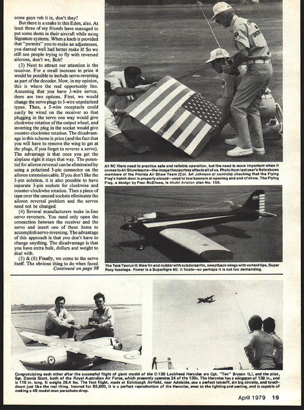
This is the point where Bob's eyes lit up! "I'll bet that the ACE R/C Bantam Midget machinery will fit in the regular Bantam case," he says, "and leave enough room for a servo reverser. Why don't you see what you can do with that idea, George?" We kicked around some possibilities until it was time to get back to work. A few days later a Bantam case and a Bantam Midget servo appeared on my desk as if by magic. "Christmas came a bit early this year!" I thought, until Bob told me he wanted them back, "after you've finished with the reversing switch."
My first thought was to make use of a 16-pin DIP switch. After a little consideration of the possibilities that left open for a direct short across the batteries, I dropped the idea. Besides, the switch was too big! Next, I tried the 4PDT Noble switch that is commonly used in switch harnesses for RC systems. It can be made to fit, with only a little help from a Dremel. The only problem is that you will have to take out the servo to get at the switch. A smaller switch could be mounted right out in the open where you can get at it, but I couldn't find one.
Slightly later Bob left another goodie on my desk: a prototype servo reverser from ACE R/C. With a few mods, this could fit in the space available. You would be left with a servo having two pigtails, one for each rotation. Plug in the one you need! This is the configuration I left the project in, when I returned the servo to Bob. One must be careful not to let the unused plug short out on any metal parts, because that will short out the batteries and kill the whole system.
As I said before, I like the idea of having the servo reverser in the receiver. With today's IC circuitry, the major configuration change would be adding the second set of sockets for the other rotation.
Additional notes and preferred approach
It's only fair to mention that Kraft has been shipping sets for 10 years that have two servos set up for each direction. (Editor's Note — Like this feature on our Cox-Sanwa.) You get what you want by swapping around the "dot" and the "no dot" servos. (The "dot" is a tiny circle molded on the mounting flange between the cutouts for the grommets.) Once you get the flight pack set up right, there's no way to make a mistake with it. That's the way I like to do things. Over the years I have bought more flight packs than transmitters. I work with the plane until the control trims and throws are right and then leave everything alone until it needs service. That way I can pick a plane off the wall and go flying without worrying if it's compatible with the transmitter. If the crystals match, it will work. In this way, one becomes familiar, and comfortable, with the transmitter "feel." In a very short time flying becomes automatic.
Reversing at the control surface (7)
Oh, you want to know about reversing at the control surface! You can cross the aileron pushrods, or put the rudder control horn on the opposite side. Great ideas, if you think of them when you are building! The same goes for the elevator. You could put the control horn on top, where it belongs. Then, when pulling out of a dive (which puts the highest load on the elevator pushrod) the rod would be in tension rather than compression, so it couldn't buckle at the worst possible moment.
Closing
Keep those letters coming, friends. I've been fortunate enough to receive some very nice ones recently. One worth mentioning came from Ron Smith, AMA 83995 & WA4JNX. Ron sent me an Official Membership Certificate (Honorary) in the Tarrant Amateur Repeater Assoc., contingent on my obtaining the Technician's License I spoke of in an earlier column. I will have more to tell you on obtaining the Tech License soon, and I think that you will like what you see and hear. Keep watching.
George Myers 70 Froehlich Farm Rd., Hicksville, NY 11801
RC Technique / Myers continued from page 19
Transcribed from original scans by AI. Minor OCR errors may remain.

