

Radio Technique — George Myers
Reader question
Each week I receive two or three nice letters from readers. Some of them ask questions that become the nucleus of a column. Here is a letter from Tom Waller of the Blue Angels R/C Club which asks a question that seems to be making the rounds:
"I'm building a Sig-designed Piper J-3 Cub. By that I mean I'm using the plans from the kit, but otherwise it's scratch-built. Since it has a 72‑in. wingspan I want to install individual aileron servos out in each wing. This may allow induction of stray RF currents in the long (almost 24 inches in each wing panel) servo leads. I've read somewhere that to prevent it one should use choke coils in the leads. OK! But what size and how many? If so, where? In all three wires? At the servo end or the receiver end?
"Next question: How about shielded leads? If so, will it be necessary to tie the shields together? Where? Should they be connected to any part of the servo circuit? Where, and how?..."
The letter continues with other matters, including the comment that "...as editor of our club newsletter, I get almost no feedback." I know what you mean, Tom. I've edited a few of them in my time, and had the same complaint. All newsletter editors have. So, if you are reading this, go over to your editor and tell him how much you appreciate what he's doing for you.
What is a choke?
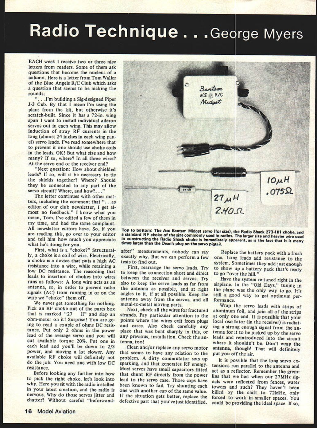
First, what is a "choke?" Structurally, a choke is a coil of wire. Electrically, a choke is a device that puts a high AC resistance into a wire while retaining a low DC resistance. The reasoning that leads to insertion of chokes into wires runs as follows: a long wire acts as an antenna, so, in order to prevent radio signals (AC) from running in or on the wire we "choke" them off.
We never get something for nothing. Pick an RF choke out of the parts box that is marked "27 µH" and slap an ohm‑meter on it. Surprise — you are going to read a couple of ohms DC resistance. Put only 2 ohms in the power lead of the average servo and you will cut available torque about 20%. Put one in each lead and you'll be down to roughly 2/3 power, and the servo will move a lot slower. Any available RF choke will definitely not do the job — you need one with low DC resistance.
Why the trouble? — basic diagnosis
Before looking further into how to pick the right choke, let's look into why the radio might be nervous. Why do those servos jitter and chatter? Without careful "before-and-after" measurements, nobody can say exactly why. But you can perform a few tests to find out.
Try the following checks and fixes, in roughly this order:
- Rearrange the servo leads. Keep the connection short and direct between the receiver and servos.
- Keep servo leads as far from the antenna as possible, and run them at right angles to the antenna if you can.
- Keep the antenna away from servos and all metal-to-metal moving parts.
- Check all wires for fractured strands, especially where wires exit plugs and cases and at any sharp bends.
- Check the antenna for damage or poor connection; clean or replace if necessary.
- Clean or replace any suspect servo motor. Dirt on the commutator can cause sparking, which generates RF energy.
- Many servos have small capacitors fitted to shunt RF to the servo case; these caps can fail. Try shunting the questionable servo with another cap of the same value — if things improve, replace the defective part.
- Replace the battery pack with a fresh one. Old packs and long leads add resistance that can reveal marginal performance.
- Have the system retuned in the airplane (tune with the radio installed). This "in-the-plane" tuning still gives best performance.
- Wrap the servo leads with strips of aluminum foil and join all the strips at only one end to form a shield. (Do not wrap the antenna.) A strong local oscillator in the receiver can radiate signals picked up by long servo leads; a one-ended foil shield can help.
- Consider that long servo extensions running parallel to the antenna may act as reflectors. Try rerouting the antenna (for example, down a tube in the wing or routed differently around the tail) to change coupling and reflections.
If you've done all of the above and the radio is still jittery, consider trying another radio or having a friendly local Amateur Radio operator (Ham) help you troubleshoot. It is sometimes the transmitter or receiver itself that is at fault.
When to try a choke (and how)
If nothing else cures the problem, it's time to try a choke.
- Begin with a general-purpose choke such as Radio Shack item No. 273-101 rated 0.1 mH (100 µH), 15 amps.
- Cut the positive lead of the long extension cable about 1 inch from the end plug at the receiver.
- Connect the cut ends to the choke and solder in place.
- Test the system. If the problem goes away, fine. If not, try putting the negative lead through the choke also.
- Do NOT put the control signal (servo) lead through the choke — wrapping the control lead can round off the control pulses and introduce a different kind of trouble.
- You may find it helpful to connect a 0.1 µF capacitor across the power leads (positive to negative) near the receiver to bypass RF. The idea is to shunt across your power supply lines with a reactance that is less than the internal resistance of the battery pack. Note that reactance of both the choke and capacitor depends on the RF frequency, and we usually assume the interfering signal is near the transmitter frequency (e.g., about 72 MHz).
Be aware that nickel‑cadmium batteries have very low characteristic impedance when in good condition. A signal coming in on the power leads would have to be fairly high voltage to overcome the low impedance, so large induced voltages are harder to find in normal RC situations. If you still have trouble after the checks above, you may have a significant fault that benefits from a Ham's help to find.
Shielded leads and harnesses
- Shielded leads can help in some installations. If you use shielded cable, tie the shield at one end only (typically at the receiver end) to avoid ground loops that can reintroduce noise.
- Do not tie shields together at both ends unless you know the grounding arrangement and it is necessary for your system.
- Do not connect shields to servo signal lines or otherwise disturb the control pulses.
Some manufacturers provide harnesses with proper chokes installed. For example, Kraft offered a special harness (No. 200-193) containing chokes of the proper size and current rating — they used 22 µH high-current chokes in that harness. You must specify the system and connector types because patterns vary. Some factories might make custom leads for other brands if you ask.
The February 1979 issue of QST magazine had a feature on a device called the Incon, a possible choke/filter solution; at the time it wasn't in production, so you might have to build one yourself.
Final notes
We are dealing with EMI (electromagnetic interference). According to experts, getting rid of EMI is more of an art than a science, but most problems occur in the low-tech area and can be cured by common-sense precautions described above. My flying buddy, Nick Ziroli, who has built and flown everything from 1/2A models to 200‑pound RPV's, says he has never found the need for chokes in any set that was working correctly before installation. So, if you're having trouble, it's most likely caused by wear, damage, poor wiring, or installation mistakes — and those usually yield to the checks and fixes above.
Keep the letters coming, folks. I'd particularly like to hear from anyone who has solved problems.
George Myers 70 Froehlich Farm Rd. Hicksville, NY 11801
Transcribed from original scans by AI. Minor OCR errors may remain.

