
Radio Technique — George M. Myers
MYERS' Universal Gremlin-Finder. The point is—an RC system should only draw an idling current from the battery pack when it is idle. If it draws more than idle current, your battery charge will be exhausted prematurely and your equipment will be subjected to unnecessary wear.
First question: How does one find out what the idling current should be?
You might begin with the manufacturer's literature. Idle currents are usually specified in either the sales brochure or the Owner's Handbook, or both. Typically, you will find idle currents listed for each type of servo and for the receiver. Make a list of the equipment in your plane, then list the idle current next to each item, then add it all up, as in Fig. 1.
You can't find the data in the literature you have? Get hold of back issues of Flying Models magazine. My buddy, Bob Aberle, goes to a lot of trouble to put that info into every review he writes. Bob has reviewed just about every RC system there is. He's sort of the P.G.F. Chinn of the RC crowd. You don't subscribe? Try the local library and/or your flying buddies.
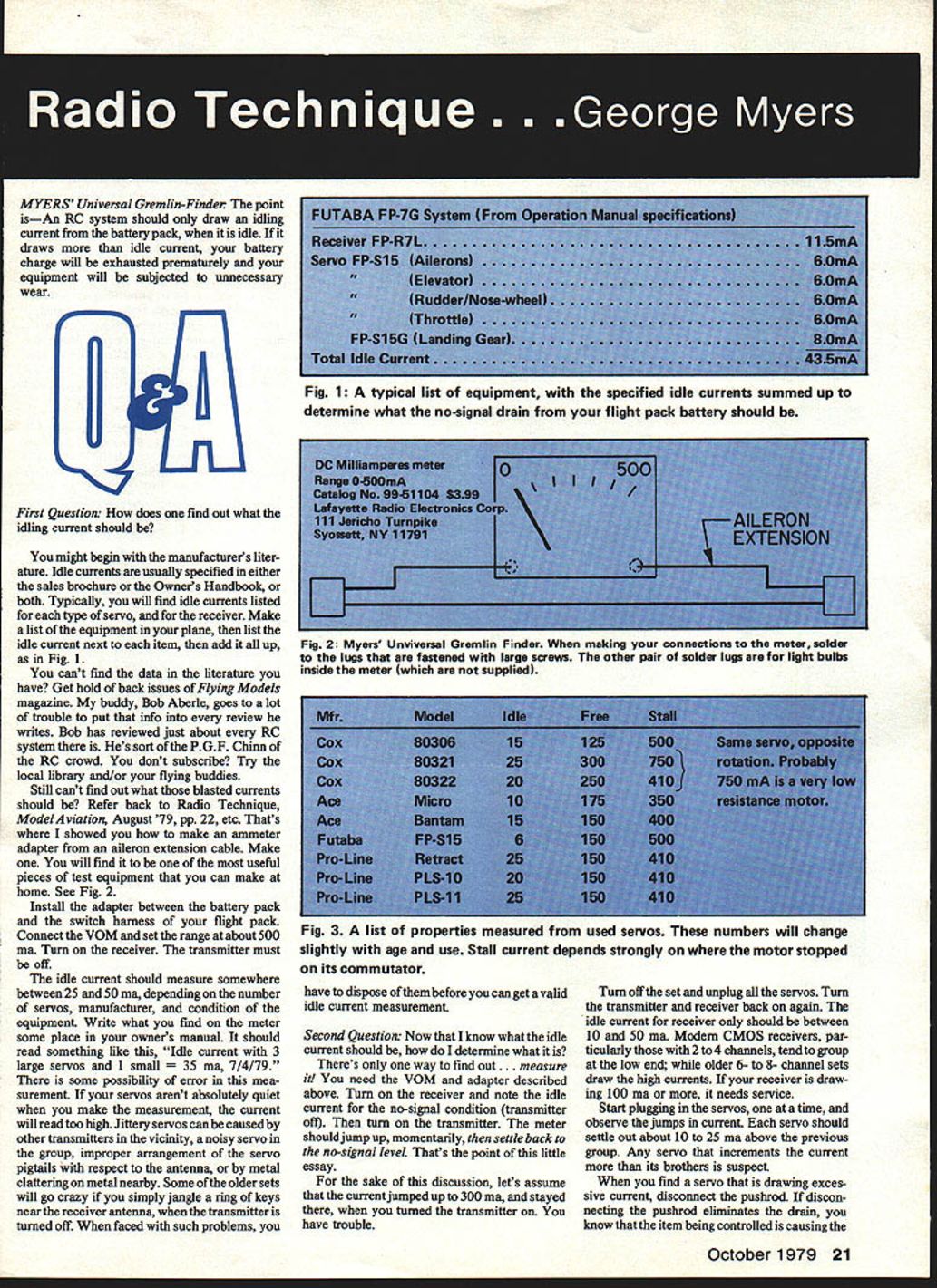
Still can't find out what those blasted currents should be? Refer back to Radio Technique, Model Aviation, August '79, pp. 22, etc. That's where I showed you how to make an ammeter adapter from an aileron extension cable. Make one. You will find it to be one of the most useful pieces of test equipment that you can make at home. See Fig. 2.
Install the adapter between the battery pack and the switch harness of your flight pack. Connect the VOM and set the range at about 500 mA. Turn on the receiver. The transmitter must be off.
The idle current should measure somewhere between 25 and 50 mA, depending on the number of servos, manufacturer, and condition of the equipment. Write what you find on the meter someplace in your owner's manual. It should read something like this: "Idle current with 3 large servos and 1 small = 35 mA," 7/4/79.
There is some possibility of error in this measurement. If your servos aren't absolutely quiet when you make the measurement, the current will read too high. Jittery servos can be caused by other transmitters in the vicinity, a noisy servo in the group, improper arrangement of the servo pigtails with respect to the antenna, or by metal clattering on metal nearby. Some of the older sets will go crazy if you simply jangle a ring of keys near the receiver antenna when the transmitter is turned off. When faced with such problems, you have to dispose of them before you can get a valid idle current measurement.
Fig. 1: A typical list of equipment, with the specified idle currents summed up to determine what the no-signal drain from your flight pack battery should be.
Fig. 2: Myers' Universal Gremlin Finder. When making your connections to the meter, solder to the lugs that are fastened with large screws. The other pair of solder lugs are for light bulbs inside the meter (which are not supplied).
Second question: Now that I know what the idle current should be, how do I determine what it is?
There's only one way to find out... measure it! You need the VOM and the adapter described above. Turn on the receiver and note the idle current for the no-signal condition (transmitter off). Then turn on the transmitter. The meter should jump up momentarily, then settle back to the no-signal level. That's the point of this little essay.
For the sake of this discussion, let's assume that the current jumped up to 300 mA and stayed there when you turned the transmitter on. You have trouble.
Turn off the set and unplug all the servos. Turn the transmitter and receiver back on again. The idle current for receiver only should be between 10 and 50 mA. Modern CMOS receivers, particularly those with 2 to 4 channels, tend to group at the low end; older 6- to 8-channel sets draw the higher currents. If your receiver is drawing 100 mA or more, it needs service.
Start plugging in the servos, one at a time, and observe the jumps in current. Each servo should settle out about 10 to 25 mA above the previous group. Any servo that increments the current more than its brothers is suspect.
When you find a servo that is drawing excessive current, disconnect the pushrod. If disconnecting the pushrod eliminates the drain, you know that the item being controlled is causing the trouble.
Fig. 3: A list of properties measured from used servos. These numbers will change slightly with age and use. Stall current depends strongly on where the motor stopped on its commutator.
Some likely suspects
- Throttle servo. Many throttles contain spring-loaded barrels that close in one direction. Therefore they continuously draw a lot of current at wide-open throttle. I faced this problem on a 1971 HP61; I simply made a new, weaker spring. Another problem area is the low adjustment screw (go low on motor trim). It is entirely possible the servo ends up leaning on the screw. Again, it will draw excess current and the ammeter shows the problem. Check out the situation — see, I'm predicting problems I never knew. Incidentally, throttle over-ride devices reduce or eliminate excess current drain; the test plainly shows it.
- Combined nose-wheel/rudder servo. Everyone knows nose-wheel loads beat up a servo; it's common practice to put a bend in the pushrod or use a spring device to protect the servo. Unfortunately, you still have to make sure that the nose-wheel tiller bar doesn't bottom out anywhere in the left/right + trim range. As with the throttle servo, if the servo leans on the spring, you will use excess current.
- Landing gear retract mechanisms. It is common practice to use some form of "over-center cam" to provide a solid up-and-down lock. This leaves a load on the servo, particularly if you fail to use a 180° retract servo made especially for this service. Anyone who uses any kind of retract mechanism should perform the idle current test in both the Up and Down positions.
- Flaps, bomb release, sailplane tow-hook release, etc. Any device that might cam into position, or have limited freedom of motion, should be checked out for every position with the idle-current test.
- Rudder, elevator and ailerons. If you slowly move each control stick through its full range, including trims, stopping every few degrees to let things settle back to the idle current, this test will quickly show up epoxy in the hinges, pushrod binding, structure in the way of the control surfaces, and other little gremlins that infest the incompletely finished job. In fact, this is such a universal test that it wouldn't surprise me a bit to see someone offer a cheap ammeter kit as one more in the line of accessories "you've got to have." If someone does, do you think they'll credit the source? We'll see.
One final thought to help you analyze your problems. Any servo has three different characteristic currents, according to what it is doing:
- Idle (about 10 mA) — energized, stationary, no signal.
- Free (150–250 mA) — running, no mechanism connected to it.
- Stalled (about 450 mA) — trying to push an immovable object.
These numbers will vary a little from manufacturer to manufacturer, and among servo types, but not much. While writing this column, I measured a bunch of used servos and tabulated the results in Fig. 3. Use the data as an example of what to expect, not as a shopping guide.
Warning
After you use this little gem, you may be tempted to build it right into the airplane. Don't! The meter is too delicate to stand up to engine vibrations. If the meter fails, all current to the flight pack is lost. Crash!
Keep the letters coming, folks! If you haven't done it yet, fill out and send in the reader survey form printed on page 8 of the August 1979 issue. Thanks.
George M. Myers 70 Froehlich Farm Rd. Hicksville, NY 11801
Transcribed from original scans by AI. Minor OCR errors may remain.

