
Radio Technique
George Myers
I'm more behind the deadline than ever before, struggling to put the results of a month of experimenting into 1,500 words. Bear with me; something good may come out of it!
The whole thing began with several reader requests for a simple way to evaluate a servo. We all noticed that servos slow down, lose torque, get noisy and begin to interfere with other system electronics as they age. At some point repair or replacement becomes necessary. The trick is to find that point while the plane is sitting on the workbench.
Most folks intuitively decide a simple torque meter will solve the problem. They look for something that can be pressed down over the servo, while it is in the airplane, that will detect a servo about to go over the hill. I built a few. They don't do the job. By the time the torque meter shows (with certainty) that performance is down, you can see the lost performance without it. Besides, you don't want to go twisting the servo output arm when the servo is resisting — it's too easy to damage gear teeth that way. I speak from experience.
My criteria for a useful test are:
- The test shouldn't damage the test article.
- The test results should be specific in defining good vs. bad.
- The tools should be readily available and useable by people who have no interest in electronics.
- The test should be possible in the plane, so it can be conducted without removing the RC installation.
- The test should be simple to perform.
Solution: the transit-time test
The solution I settled on is the transit-time test. The purpose is to determine whether transit time — the time in seconds required for a servo to move its output arm through a specified angle — has changed.
Tools required
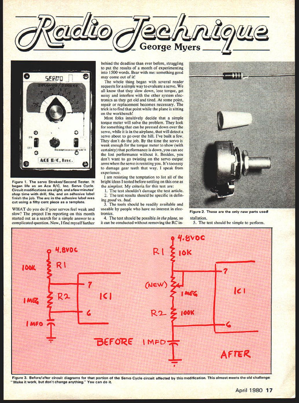
- An Ace R/C, Inc. Servo Cycle, modified to measure transit time.
- A corner clipped off a business card to provide a 90° reference to set servo stroke.
- Your thumbnail.
- A stopwatch.
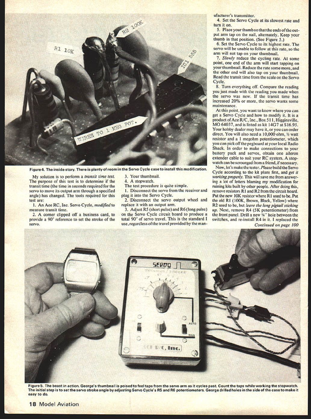
- A 10,000-ohm resistor and a 1-megohm potentiometer (available at Radio Shack).
- Battery pack, servos, an aileron extender cable to suit your R/C system.
You can obtain a Servo Cycle kit from Ace R/C, Inc., Box 511, Higginsville, MO 64037. The listed kit (14G7) is $16.95. Your hobby dealer may have it or can order direct.
Test procedure
- Disconnect the servo from the receiver and plug it into the Servo Cycle.
- Remove the servo output wheel and replace it with the output arm.
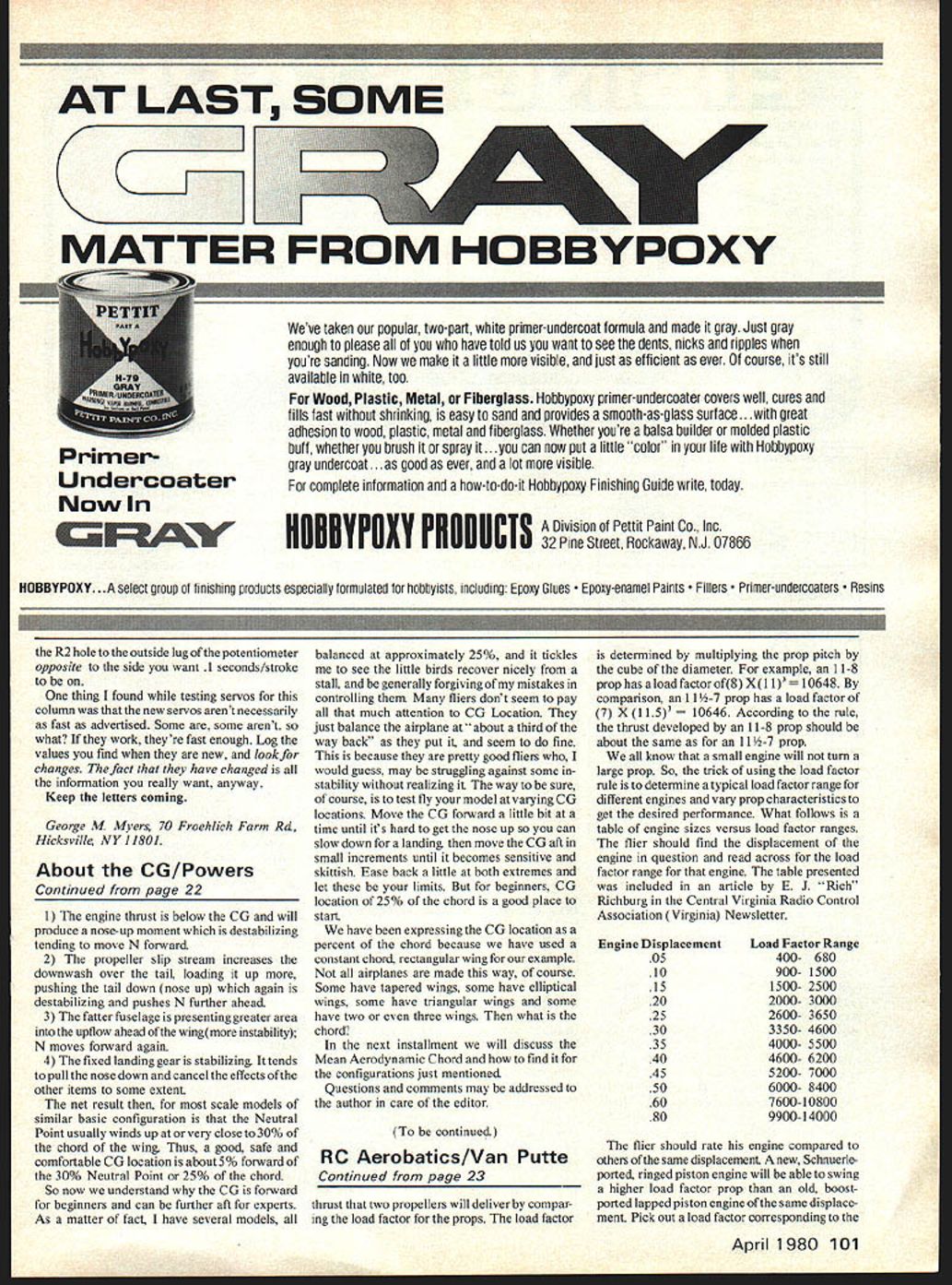
- Adjust R5 (short pulse) and R6 (long pulse) on the Servo Cycle circuit board to produce a total 90° servo travel. Use this 90° standard regardless of the travel provided by the manufacturer's transmitter.
- Set the Servo Cycle to its slowest rate and turn it on.
- Place your thumbnail so the ends of the output arm will tap alternately on the nail. Keep your thumbnail in that position.
- Set the Servo Cycle to its highest rate. The servo will be unable to follow at this rate and the arm will not tap the thumbnail.
- Slowly reduce the cycling rate. At some point one end of the arm will start tapping the thumbnail. Reduce the rate until the other end also taps the thumbnail. Read the transit-time scale on the Servo Cycle.
- Turn everything off. Compare the reading just made with the reading taken when the servo was new. If transit time has increased by 20% or more, the servo needs maintenance.
Calibration tip: when first setting up, use the corner-clipped business card to set the 90° travel precisely.
Modifying and building the tester
- Build the Servo Cycle kit according to the kit plans first and get it working properly.
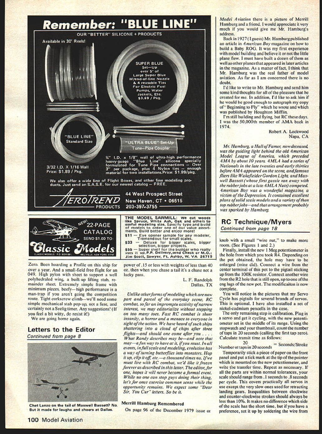
- After verifying the kit, remove resistors R1 and R2 from the circuit board.
- Install a new 10K resistor where R1 was.
- Put the old R1 (100K, brown-black-yellow) where R2 was and leave a long pigtail sticking up.
- Remove the R4 5K potentiometer from the front panel. Drill a new hole between the switches and re-install the replaced R4.
Note: Some units have pigtails for several brands of servos — this is optional. I also installed a set of nickel-cadmium battery pencils in the case.
Calibration
- Plug in a servo and get it cycling, with the new potentiometer set in the middle of its range.
- Using the stopwatch and your thumbnail, count the number of taps in 20 seconds (calling the first tap zero).
- Calculate transit time as follows:
Seconds per stroke = 20 ÷ (number of taps in 20 seconds)
- Temporarily stick a piece of paper on the front panel and mark the tip of the pointer mounted on the new potentiometer with the calculated transit time. Repeat as necessary.
If all parts are within normal tolerances, your unit will range from about 0.1 seconds to 0.8 seconds per cycle — covering practically all servos in common use except very slow retract servos. Inequality between clockwise and counterclockwise strokes should be less than 10%. It makes no difference which side of the scale has the short time; if you have a preference, set it up by soldering the wire from the pot to the left or right lug.
Calibration takes less than five minutes per servo.
Notes and recommendations
- During testing I found new servos aren't necessarily as fast as advertised. Some are, some aren't. If they work for your application, they're fast enough.
- Log the values you find when a servo is new and look for changes over time. The fact the value has changed is the information you want.
- If transit time increases by 20% or more, perform maintenance or replace the servo.
Keep the letters coming.
George M. Myers 70 Froehlich Farm Rd. Hicksville, NY 11801
Transcribed from original scans by AI. Minor OCR errors may remain.

