

Radio Technique
George Myers
The Ace R/C Experimenter's Special
The Ace R/C Experimenter's Special. Have you seen all the new radios with switches, mixers, meters and other goodies covering the surface of the transmitter? Have you thought:
- I'd like to show off like that, but who can afford to?
- It would take forever to learn how to fly that way. You'd practically need an instrument ticket.
- I could find a more sensible way to do things than that.
- How can I get my hands on one to try it?
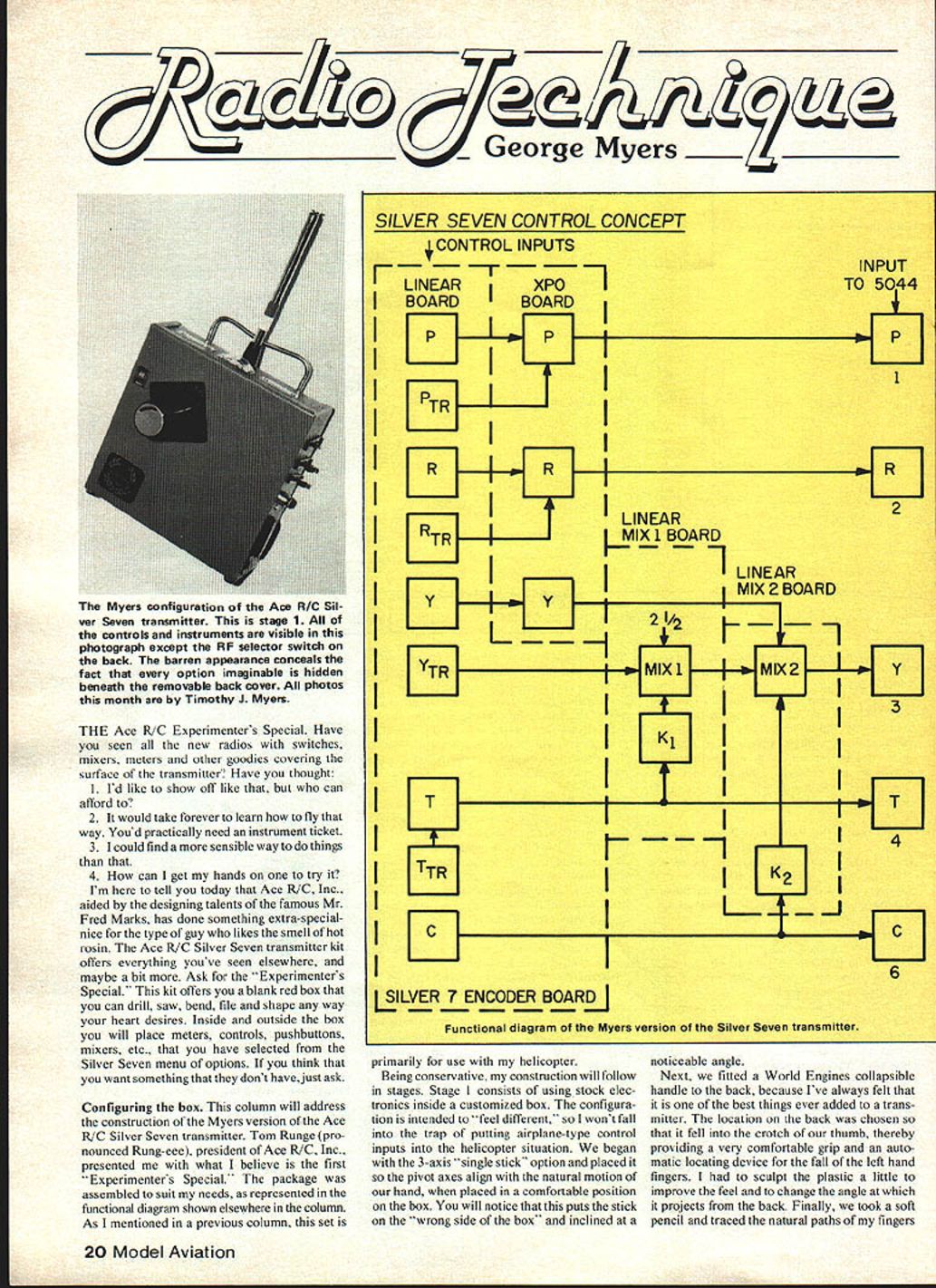
I'm here to tell you today that Ace R/C, Inc., aided by the designing talents of the famous Mr. Fred Marks, has done something extra-special for the type of guy who likes the smell of hot rosin. The Ace R/C Silver Seven transmitter kit offers everything you've seen elsewhere, and maybe a bit more. Ask for the "Experimenter's Special." This kit offers you a blank red box that you can drill, saw, bend, file and shape any way your heart desires. Inside and outside the box you will place meters, controls, pushbuttons, mixers, etc., that you have selected from the Silver Seven menu of options. If you think that you want something that they don't have, just ask.
Configuring the box
This column will address the construction of the Myers version of the Ace R/C Silver Seven transmitter. Tom Runge (pronounced Rung-gee), president of Ace R/C, Inc., presented me with what I believe is the first "Experimenter's Special." The package was assembled to suit my needs, as represented in the functional diagram shown elsewhere in the column.
As I mentioned in a previous column, this set is primarily for use with my helicopter.
Being conservative, my construction will follow in stages. Stage 1 consists of using stock electronics inside a customized box. The configuration is intended to "feel different," so I won't fall into the trap of putting airplane-type control inputs into the helicopter situation. We began with the 3-axis "single-stick" option and placed it so the pivot axes align with the natural motion of our hand, when placed in a comfortable position on the box. You will notice that this puts the stick on the "wrong side of the box" and inclined at a noticeable angle.
Next, we fitted a World Engines collapsible handle to the back, because I've always felt that it is one of the best things ever added to a transmitter. The location on the back was chosen so that it fell into the crotch of our thumb, thereby providing a very comfortable grip and an automatic locating device for the fall of the left hand fingers. I had to sculpt the plastic a little to improve the feel and to change the angle at which it projects from the back. Finally, we took a soft pencil and traced the natural paths of my fingers.
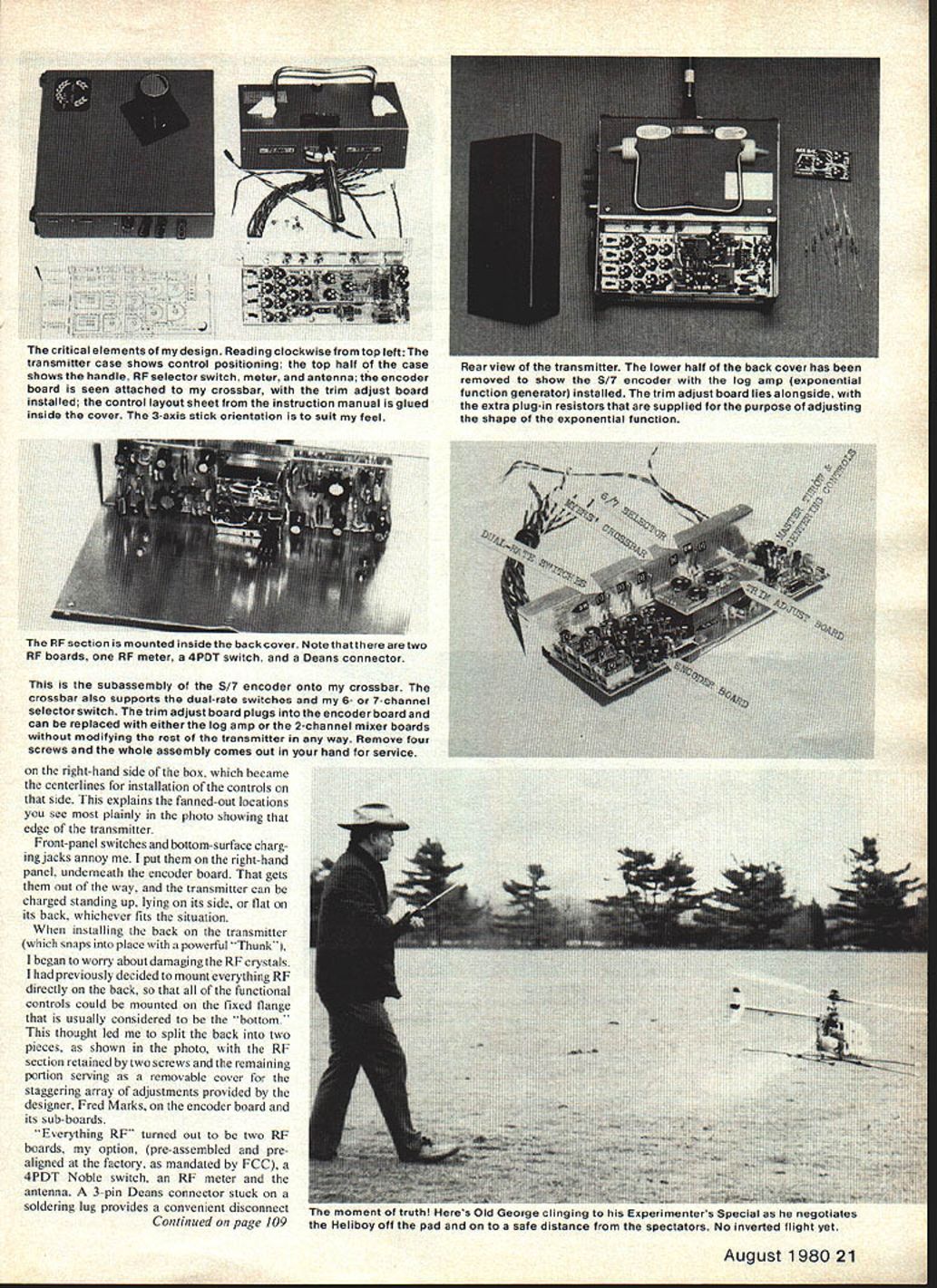
The RF section is mounted inside the back cover. Note that there are two RF boards, one RF meter, a 4PDT switch, and a Deans connector.
This is the subassembly of the S/7 encoder onto my crossbar. The crossbar also supports the dual-rate switches and my 6- or 7-channel selector switch. The trim adjust board plugs into the encoder board and can be replaced with either the log amp or the 2-channel mixer boards without modifying the rest of the transmitter in any way. Remove four screws and the whole assembly comes out in your hand for service.
The right-hand side of the box became the centerline for installation of the controls on that side. This explains the fanned-out locations you see most plainly in the photo showing the edge of the transmitter.
Front-panel switches and bottom-surface charging jacks annoy me. I put them on the right-hand panel, underneath the encoder board. That gets them out of the way, and the transmitter can be charged standing up, lying on its side, or flat on its back, whichever fits the situation.
When installing the back on the transmitter (which snaps into place with a powerful "Thunk"), I began to worry about damaging the RF crystals. I had previously decided to mount everything RF directly on the back, so that all of the functional controls could be mounted on the fixed flange that is usually considered to be the "bottom." This thought led me to split the back into two pieces, with the RF section retained by two screws and the remaining portion serving as a removable cover for the staggering array of adjustments provided by the designer, Fred Marks, on the encoder board and its sub-boards.
"Everything RF" turned out to be two RF boards, my option (pre-assembled and pre-aligned at the factory, as mandated by the FCC), a 4PDT Noble switch, an RF meter and the antenna. A 3-pin Deans connector stuck on a soldering lug provides a convenient disconnect point for the battery voltage and modulation signal. It's wired so that everything switches to the RF board in use. We wondered if the antenna would be substantially supported in this situation, but don't give it another thought. You could use it to drive nails! Everything is a tiny bit off center to put the antenna over its part of the switch and to make sufficient clearance for the controls on the right-hand panel.
Setting up the back this way forced me to include the crossbar, which was chopped and pounded out of a piece of soft .090 dural. This became the natural support for the encoder board and the several switches. My experiences with a dual-rate transmitter convinced me that switches on the outside of the box get knocked out of position too easily, so I put them inside. You will notice that the encoder board is upside down. It is intended to be mounted on the bottom of the box, but there is no bottom on my case, and there's no room on the encoder board to put mounting holes along the other edge. So, I pounded the "L"-shaped mounting clips flat (which were provided by Ace R/C for the purpose of mounting the board off the bottom of their box) and used them to tie the board to my crossbar. The batteries were taped in place, as intended by the manufacturer, leaving space on each side for wires, switches, etc. It makes a very neat installation, as you see.
Soldering the parts together
Each of the circuit boards provided was wired exactly per the instructions. Then the controls were connected, and I again used the instructions, wires and color codes. Why make life any more difficult than it has to be? Alignment also followed the Ace R/C instructions, with the result that everything worked right the first time.
You may have noticed that there isn't any "Solder Wire A to Lug B" description here. If you really need it, write to Ace R/C, Inc., Box 511E, Higginsville, MO 64037, and tell them I told you to ask for a construction manual (116507, $2). You will find that it's very complete.
The point of this column is that Ace makes it very easy for you to build up a "Super Transmitter" in whatever configuration pleases you, and at very little cost.
Checkout
What follows is essentially a factory checkout procedure checklist for the Myers version (+) of the Ace R/C Silver Seven transmitter:
- Antenna
- 5 1/4" collapsed, 40 1/4" extended.
- All sections are electrically connected.
- Back
- Upper section securely attached and grounded to box.
- Lower section securely attached and easily removable.
- Carrying handle
- Check fit in 3 positions.
- On/on switch
- Check function, leakage, isolation.
- Charging jack
- Check function, leakage, isolation.
- Battery capacity
- Show 600 mAH @ 2-hour discharge rate.
- Operating current
- Encoder only: 33 mA.
- Complete transmitter: 135 mA.
- Operating time
- 4-1/2 hours from fully charged pack.
- ESV meter indications
- Green scale: 11.0 to 9.8 VDC.
- Red scale: 9.8 to 8.5 VDC.
- RF bandwidth
- Check function, leakage, isolation.
- RF output
- Show 750 mW at 72.080 and 72.240 MHz.
- RF output meter
- Show full scale deflection @ 11.0 VDC from the battery pack.
- Mechanical controls & adjustments
- Check and adjust for range of motion, spring force, binding, as required.
Control Channel Numbers
- Channels: 1 2 3 4 5 6 7
- Primary Control: X X X X X X X
- Primary Control Center: X X X X
- Trim Control: X X X
(X = Adjust per Ace R/C instructions)
- Electrical adjustments
- See Construction Manual.
Master Throw / Adjustments (indications of which controls affect which channels)
- Master Centering: Channels 1 2 3 4 5 6 7
- Reversing Switch: Channels 1 2 3 4
- Dual Rate Switch: Channels 1 2 3 4
- Plug-In Boards: Channels 1 2 3 4
- Jumpers: Channels 1 2 3 4 5
- 6/7 Channel Switch: Channels 1 3
- Servo Center Adjustment: Channels 1 2 3 4
- Servo Range Adjustment: Channels 1 2 3 4 5 Hi/Lo
- Trim Range Adjustment: Channels 1 2
- D/R Servo Range: Channels 3 4 3
- Exponential Shape: Channels 4 4 4 4
(Number refers to notes below.)
(The following will be added in Stage 2.)
- Mixer 1
- Control Range Adjustment: Channels 1 2 3 4
- A + B: Channels 1 2
- Direct B: Channels 1 2
- Mixer 2
- Control Range Adjustment: Channels 1 2 3
- A + B: Channels 1 2 3
- Direct B: Channels 1 2 3
- Audio Timer
- 3 to 30 min. adjustable time.
Notes
- Trim Range is a screwdriver adjustment when the Trim Adjust Board is installed. Trim Range is fixed by R9 on the Exponential Function Board, when it is used. R9 can be changed to vary the Trim Range.
- Trim Range for channel 4 is set by a plug-in resistor on the encoder board, which can be changed to suit your preferences. The range of adjustment is approximately ±0% to ±50% in all cases.
- The Dual Rate function applies to both linear and exponential control functions on channels 1, 2 and 3. A Linear/Exponential Switch can also be fitted, if desired.
- The exponential function can be adjusted by changing plug-in resistors R4 and R5 on the Exponential Function Board.
- Not applicable to switched functions.
Using it
Alright, now that it's built, what can we do with it? By adjusting the Master Throw and the Master Centering controls, we can make our transmitter control systems as different as the Futaba Contest 7 (7 channels, 1.31 milliseconds neutral pulse) and the Kraft Sport (4 channels, 1.9 ms neutral). That's a pretty wide range, but I know it works because I've done it.
Having made the adjustments, we thereby convert an uncomplicated system (like the Kraft Sport, for instance) into one with servo reversing, dual rate, exponential control, adjustable trim range, V-tail mixing and a host of other refinements.
That last sentence tells it all, so read it again. The thing to do is for me to learn to fly the Heliboy with the new box, but still using the mechanical mixers which were provided by Schluter. I'd like to tell you that I went right out and flew like an expert, but that would be a lie. This transmitter feels so different (on purpose, mind you) that it put me right back to square one. But consider this: If I don't like it, all I need do is buy another box and repackage the components. Watch for Stage 2 in a later column.
Before signing off, I really must thank Tim Peters of Jennings, KS, for his suggestions (most of which have already been included in the design, as he will see) and Dave Chesney for his helpful suggestions and encouragement. Also, Ed Farabaugh for his extensive list of safety considerations, which I expect will show up in John Preston's column. The rest of you, keep writing and looking. If I don't answer personally, you may find it answered here. Thanks to all.
George M. Myers 70 Froehlich Farm Road Hicksville, NY 11801
Transcribed from original scans by AI. Minor OCR errors may remain.

