
Radio Technique
George Myers
"SAY, GEORGE, when are you going to quit playing with that red box and get back to flying like the rest of us?"
"When I stop having so much fun doing what I'm doing, that's when!"
The August 1980 column dealt with construction of a standard Ace R/C Silver Seven transmitter kit inside a customized box. That was an example of what you might do with the Silver Seven "Designer's Package," available from Ace R/C, Inc., Box 511E, Higginsville, MO 64037. We promised to continue to "stage 2," which customizes the electronics. Fundamental to the customizing process is the design of a dual mixer, which I discuss here.
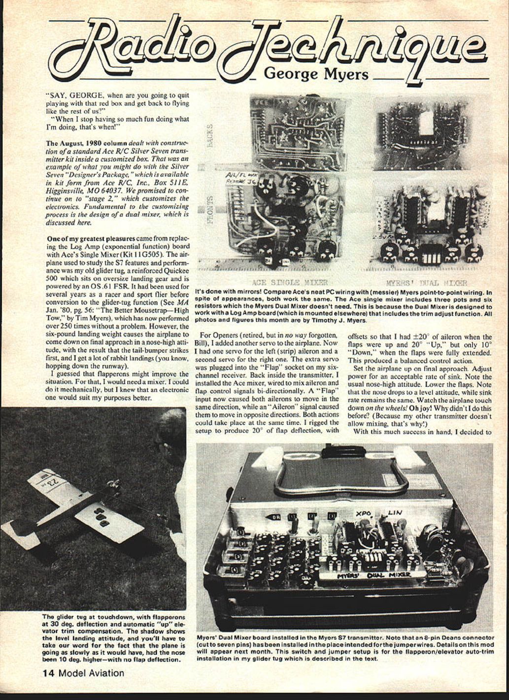
One of my greatest pleasures came from replacing the Log Amp (exponential function) board with Ace's Single Mixer (Kit 11G505). The airplane used to study the S7 features and performance was my old glider tug, a reinforced Quickee 500 on oversize landing gear, powered by an OS .61 FSR. It had been used for several years as a racer and sport flier before conversion to the glider-tug role (see MA Jan. '80, pg. 56: "The Better Mousetrap—High Tow," by Tim Myers). The tug has performed over 250 tows without a problem. However, the six-pound landing weight causes the airplane to come down on final approach in a nose-high attitude so the tail-bumper strikes first, producing a lot of "rabbit" (hopping) landings.
I guessed that flapperons might improve the situation. For that I would need a mixer. I could do it mechanically, but an electronic mixer would suit my purposes better.
Modifying the S7 for flapperons
- I added another servo: one servo for the left aileron (strip) and a second for the right. The extra servo plugged into the "Flap" socket on my six-channel receiver.
- Inside the transmitter I installed the Ace mixer, wired to mix aileron and flap control signals bi-directionally:
- A "Flap" input caused both ailerons to move the same direction (flap function).
- An "Aileron" signal caused them to move in opposite directions (ailerons).
- Both actions could occur simultaneously.
- I rigged the setup to produce 20° of flap deflection, with offsets so I had ±20° of aileron when the flaps were up, and 20° Up / only 10° Down when the flaps were fully extended. This produced a balanced control action.
Flight results
- On final approach with power adjusted for an acceptable sink rate, the usual nose-high attitude dropped to level when the flaps were lowered, while the sink rate remained the same.
- The airplane touched down on the wheels instead of the tail bumper. Success.
Expanding the idea: dual mixers and exponential control
- The Ace Single Mixer makes mixing two signals (for example, flap and aileron) easy. The stock Silver Seven (S7) arrangement permits only certain mixer configurations, and I wanted a system that would provide exponential (XPO) control for two mixers.
- I made two modifications:
- Compact two Ace mixers onto one board.
- Install the Log Amp board in another location and modify the encoder board to route control signals through it. (Details of the encoder modification and log-amp relocation will appear in a later column.)
- One interesting point: combining XPO and LIN signals works fine. The S7 and other transmitters that use the NE5044 chip provide parallel continuous analog voltages, so it's easy to mix and combine signals.
- Older transmitter designs used a "string-of-dominoes" approach to control signal generation. By the time you got to the flap function, for example, the aileron control signal could be gone. Radios without parallel/continuous voltages don't have mixers and cannot accept an Ace mixer without substantial modification.
Practical cautions about mixing
- You can't simply drop a mixer into an S7 and go flying. Considerations:
- Servo direction (normal or reversed).
- Servo throw differences — not all servos respond the same.
- Many adjustments are required; when you interconnect two mixers you multiply the number of adjustments.
- Make detailed notes of the final settings so you can duplicate them later.
My final mixer settings and connections (my shorthand) F = M1A & M2A Y
- Flap control signal goes to Mixer 1 input A and Mixer 2 input A via a "Y" adapter.
Other shorthand entries:
- A -> M1B
- E -> M2B
- M1L -> C1 (Mixer 1 output 1 goes to control input 1)
- M12 -> C6
- M1 = bi (Mixer 1 is bi-directional)
- M2L -> X (X = not used)
- M22 -> C2
- M1A = 1:30 (Mixer 1 input attenuator A set to 1:30 o'clock)
- M1B = 2:00
- M1C = 12:00 (balance pot centered)
- M2A = 11:00
- M2B = 1:30
- M2C = 11:30
- M2 = uni (Mixer 2 is uni-directional)
- SE = R (Elevator servo is reversed)
- SA = N(Rt) (Aileron servo normal rotation; operates right-hand strip aileron)
- SF = R(LA) A = 1, R, X, 11:00 (Flap control: normal neutral, reversing switch set reverse; exponential engaged; servo throw adjustment at 11:00; operates left-hand strip aileron)
- E = 1, N, L, 10:00
- F = 8:00, 3:00
If you're not bored or lost by now, you must be skimming. Only someone who has been fighting with dual mixers would care. The important operational points are:
- The flaps caused a nose-down pitch; mixing flap and elevator in the second mixer corrected it.
- All mixing and adjusting was done with a screwdriver inside the transmitter — simple and convenient once you know what to adjust.
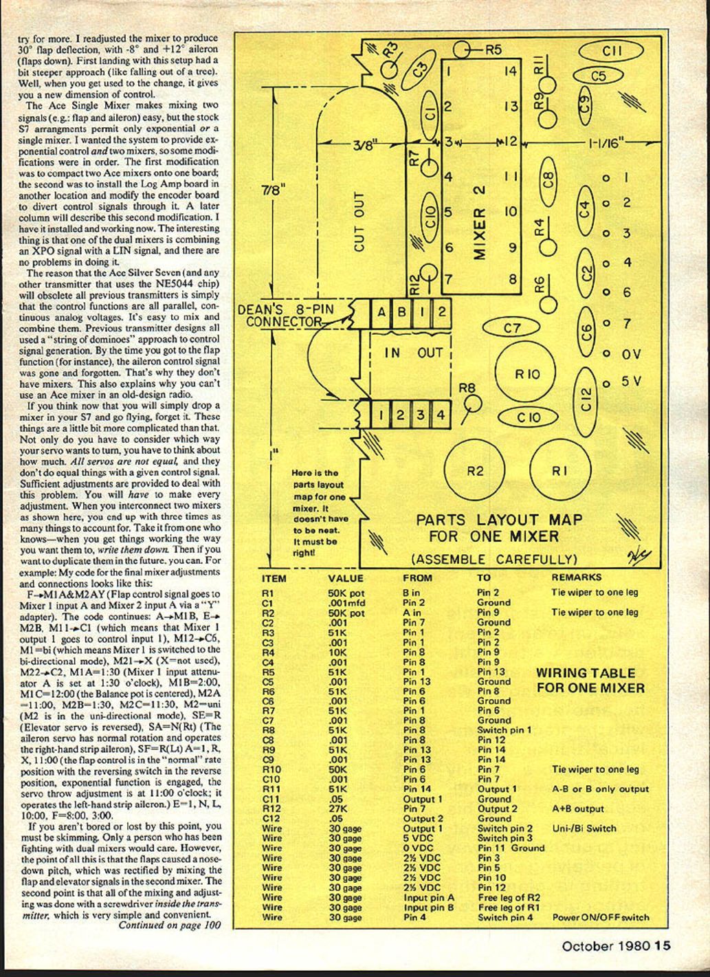
Building a dual mixer (for helicopter or other jobs) What you need (parts/tools)
- Two Ace mixer kits (11G505) and two 8-pin Deans connectors (Ace supplies them). Also a pack of hookup wire (50L520).
- A wire-wrap tool and some 30-gage wrapping wire from Radio Shack: tool #276-1570A (follow the instructions on the back). Stop winding at about four turns. Buy a 4-position DIP switch.
- A #67 twist drill and something to turn it with. You’ll also need a #60 twist drill.
- A 1-inch square of perf-board makes a handy drill guide (optional).
Assembly overview (step-by-step)
- Install the 17 mini-pins in one of the mixer boards. Bend the pins to hold them and solder on the parts side.
- Use a single-edge razor blade to file and scrape all remaining PC material off the board, including the legend (sorry, Ace).
- Drill an 8 x 12 pattern of #67 holes next to each row of pins, leaving room for the sockets that will sit under the board.
- Cut a T-shaped opening in the end of the board. File carefully — an 8-pin Deans socket fits tightly when half-submerged (they're tapered). Fit and secure the socket.
- Cut one 8-pin Deans connector down to seven pins and install it in the space intended for the jumper wires.
- Use wire-wrap to make jumpers between the two mixer boards; keep wrap turns short (about four turns).
- Mount the second mixer board on top of the first using spacers to clear the wire-wraps and sockets.
- Modify the encoder board to divert the control signals through the dual mixer assembly (detailed encoder modification will be described in a later column).
- Install the Log Amp board in its new location and wire the mixer outputs to the appropriate encoder pins. Label and check each connection.
Wiring and final assembly tips
- Cut the solder tails off the Deans about 1/16 inch high.
- Drop the components for one mixer into the holes on one side of the board. A socket for the IC is optional.
- The arrangement of resistors and capacitors isn't critical, but if you make it similar to my layout it will be easier to wire.
- Make a map of the components and label them. Wire point-to-point according to a wiring table. Check off each connection as you wrap it.
- Advantage: very compact part arrangement.
- Disadvantage: you can get hopelessly lost if you fail to follow a wiring table.
- String all grounds to a single connection at the 0-volt pin. Repeat the process for the second mixer.
- Drill eight #67 holes in the center of the empty space for the DIP switch. Use two switches to turn the mixers on/off, and the other two for uni/bi-directional switching.
- Arrange the pots to your satisfaction and drill 18 #60 holes for them.
- Clip component leads to about 1/4 inch before wire-wrapping — wiring goes much easier.
- You can wrap over other wraps and stack them. Solder everything only after you're sure it works. Watch for solder bridges.
- If you make a soldering mistake, Radio Shack's "Solder Wick" (copper braid) will remove excess solder: lay the wick on the joint, heat with the iron, and the solder flows into the wick. Clip and discard the used wick.
Switch/jumper setup and operation
- With a suitable switch/jumper setup you can select flapperon/elevator automatic-trim operation or conventional mixing.
- I readjusted the mixer to produce 30° flap deflection with -8° and +12° aileron (flaps down). The first landing with that setup had a steeper approach, but after getting used to it it provided a new dimension of control.
- Combining XPO and LIN signals posed no problems. The NE5044-based S7 provides parallel continuous analog voltages, making mixing straightforward. That's why the Ace mixer integrates well with the S7 but can't be simply dropped into older domino-chain radios.
Final notes and cautions
- If you build and install the Myers Dual Mixer in your Silver Seven, don't send the radio to Ace for repair if it doesn't work — they cannot work on a "home-brew" item like this. If you build it, you're strictly on your own.
- I will describe the encoder modification and the flapperon/elevator auto-trim installation for the glider tug in a later column. You’ll also see photos showing the second Deans socket I installed on the Silver Seven encoder board to make a patch panel.
- I’ve received letters asking for prices and sources. I’ll continue to list where I bought special items; prices change, so you pay what you must. For the rest, work through your hobby dealer and give them a chance to get the parts before you mail-order.
Keep the letters coming.
George M. Myers 70 Froehlich Farm Rd. Hicksville, NY 11801
Transcribed from original scans by AI. Minor OCR errors may remain.

