
Radio Technique
George Myers
This column is about solving problems. I'll assume you have an electronic circuit problem you want to try to fix yourself and that you accept the risk of failure. I'll describe one way to proceed, using the MPS "System Alert" as an object lesson. I received this unit for evaluation from Edward Zindle, Model Protective Systems, 279 Jefferson Ave., Buffalo, NY 14204. The System Alert inserts between the receiver and a servo to signal low battery voltage (by beeping) or that the transmitter is turned off (by a continuous buzz). It's supposed to be helpful for finding a model that has hidden under a bush or among tall corn stalks.
We installed the System Alert in my son's sailplane. Tim will fly for hours using only an Aquila, a high-start, and a Cannon micro transmitter (got to keep the field kit light when using a bicycle for transportation!). Imagine our surprise when the buzzer sounded only four times out of ten as the transmitter was turned off. It didn't make sense that Ed Zindle would send a defective unit, so there had to be some other reason. I had two choices: send it back or try to fix it myself. To keep up the image, I decided to see what I could do (besides, I like solving puzzles).
Step 1 — Figure out what the unit is supposed to do
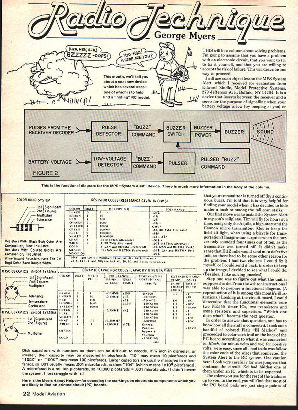
From the written instructions I prepared a functional diagram (a reproduction is among this month's illustrations). Looking at the circuit board, I could determine the functional elements: two NE555 timer ICs, two transistors, and some resistors and capacitors. The next question was, which part does what?
To answer that, you must know how everything is connected. I took out a handful of colored Flair "El Markos" and proceeded to color each trace on the back of the PC board according to what it was connected to. Black for minus volts and red for plus volts were easy since I only had to follow the color code of the wires that connected the System Alert to the RC system. One caution: look very carefully for wire jumpers that continue the circuit. Ed had hidden one under an IC, which is to be expected.
The colors you use for the rest of the traces are up to you. In the end you will find that most of the PC board pads are just single points of interconnection on the final wiring diagram. You can use the same color more than once so long as you keep the pads separated in your mind.
Make a wiring diagram
Next, draw a wiring diagram. Put the ICs and transistors on a big piece of paper, then interconnect them with symbols for resistors and capacitors. The values of resistors and capacitors are indicated by numbers and colored stripes or paint. You may run into trouble since manufacturers mark the same item differently. I've included a figure showing the most common markings; it should be adequate. If not, you have two choices: drop the project, or guess at the answer and mark it on the diagram with a question mark. I do the second.
When later analysis supports my guess, I save time. If it doesn't, the question mark warns me that I don't really know, so I can do additional research. When you have built several Ace RC or Heath kits, you'll notice that their manuals can be helpful in decoding parts markings since they include a general section on the subject. The book rack at your local Radio Shack also contains handy references, such as Modern Dictionary of Electronics by Rudolf E. Graf (Sams).
Decoding capacitors and the Myer’s Handy Helper
Disc capacitors with numbers on them can be difficult to decode. If 1/2 inch in diameter or smaller, their capacitance may be measured in picofarads. "10" may mean 10 picofarads and "100Z" or "100K" may mean 100 picofarads. Larger capacitors are usually measured in microfarads, so ".001" usually means 0.001 microfarads, as does "104" (which means 1 x 10^4 picofarads). A microfarad is a million picofarads, so 10,000 picofarads = 0.01 microfarads. (I didn't invent the system; I just struggle with it.)
Here is the Myers Handy Helper — for decoding markings on electronic components you are likely to find on printed-circuit (PC) boards.
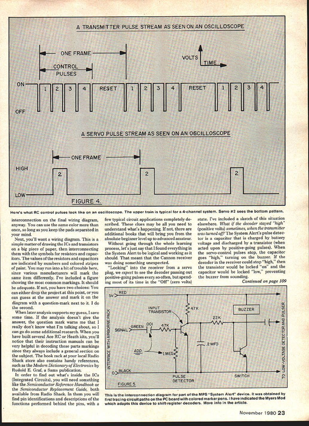
(Note: There's also a sketch elsewhere in the column showing what RC control pulses look like on an oscilloscope. The upper train is typical for a 4-channel system; servo #2 sees the bottom pattern.)
Finding what's inside ICs
To find out what's inside the ICs, you'll need references like the Semiconductor Reference Handbook or the Semiconductor Replacement Guide (both available from Radio Shack). These give pin identifications and descriptions of functions behind the pins, with a few typical circuit applications described. These clues may be all you need. If not, additional books can take you from beginner to advanced amateur.
Diagnosing the System Alert problem
Without going through the whole learning process, I found everything in the System Alert to be logical and working as it should. That meant the Cannon receiver was doing something unexpected.
Looking into the receiver from a servo plug, we expect to see the decoder output positive-going pulses every so often, but spend most of its time in the "off" (zero volts) state. What if the decoder stayed "high" (positive volts) sometimes when the transmitter was turned off? The System Alert's pulse detector is a capacitor that is charged by battery voltage and discharged by a transistor (when acted upon by positive-going pulses). When the servo-control pulses stop, the capacitor goes "high," turning on the buzzer. If the decoder in the receiver could stay "high," then the transistor would be locked on and the capacitor locked low, preventing the buzzer from sounding.
A quick check with my oscilloscope showed that was exactly what was happening. You wouldn't need an oscilloscope to see this: a 6 volt DC meter with 100K ohms or more resistance will work. Connect between the negative lead (black wire) and the signal lead (orange wire), turn on the receiver and turn the transmitter on and off a few times. Sometimes the voltmeter will read positive volts, sometimes zero, when the transmitter is off.
You may think: if it's so simple, why didn't I start with that measurement and cut out all the other stuff? Two reasons: (1) I didn't think of it at the time, and (2) I needed the System Alert wiring diagram if I wanted to make any worthwhile changes.
The fix I used
Knowing the problem, the solution was obvious. I added a 0.001 mfd capacitor in series with the System Alert green wire and a 1 megohm resistor from the base of the input transistor to ground. (These are not optimum values—just values that worked for me.) The capacitor passes the pulses but blocks DC, and the resistor ensures the input transistor turns off. So the buzzer must sound! Ed says he will make a change in production, which may differ from my values. In the meantime, if your System Alert refuses to buzz when you turn your transmitter off, give my fix a try. If your System Alert works every time (and it does with most systems without the mod), forget about it.
Another fix — frame-time resistor change
Another fix some may want to know about: the frame-time resistor on early Ace R/C Silver Seven transmitter encoders was 270K (R2, just above the NE504). It has been changed in production to 330K. The reason is to increase the frame time from 18 ms (adequate for 2–5 channel receivers) to 22 ms (necessary for 6– and 7-channel receivers). Paul Edmunds of Paul's R/C, Omaha, NE, discovered the need; the fix was worked out by Paul Holsten of Ace R/C. Tom Runge, president of Ace, wrote that the change has been made in production. If you have one of the early models, either swap a 330K for the 270K, or do what I did: put a 56K resistor in series with the 270K, with provisions for shorting it out again if the need arises.
As it happens, my son's 4-channel Cannon system uses a 16 ms frame time for the transmitter, receiver and servos, so if I want to fly on the old pack I'll need the 18 ms option. Mismatched frame times can lead to poor servo performance. It's much easier to retune the transmitter than to go inside the receiver and each servo to re-time them to match the transmitter. The beauty of the S7 is that it's easy to make whatever change you need.
What is frame time?
Frame time is the time required for one complete set of control pulses plus the required "reset" pulse. Since there is only one control pulse per channel, frame time is also the period required for repetitions of the control pulse to any individual servo. Each servo is designed to "stretch" its control pulse over the full frame time of the transmitter it is designed to work with. Therefore, a servo may work poorly with another manufacturer's transmitter because the new transmitter's frame time is either longer (causing the servo to be somewhat sloppy about staying in its "rest" position) or shorter (causing the servo to act jittery). Figuring out what frame time a servo wants can be the subject of another whole column. For now, if you mix and match servos and they don't play well together, suspect frame-time problems.
The Nats takes over the December issue, so no "Radio Technique" until next year. See you then!
George M. Myers 70 Froehlich Farm Road Hicksville, NY 11801
Transcribed from original scans by AI. Minor OCR errors may remain.

