
Radio Technique
George Myers
FROM time to time, people ask me how I keep up the flow of ideas for this column. Well, this magazine is the only one that gives you, the reader, a target (address at the end of the column). Therefore, I get at least a dozen letters per month and try to answer them. That takes a bunch of time. In order to recoup the investment, some of the questions lead to columns, on the assumption that if one person takes the time to actually sit down and write, another hundred or so "would like to, but...." If I sound enthusiastic about a product, it's because I have personally used it for a while, tested it against my expectations and against competing products, and come up with the idea that it's great. Since practically everything I write about is purchased with my own personal cash, the range of subjects is somewhat limited.
A recent letter delighted me:
".... Your layout on the dual mixers was great! But, what happened to the rest of the story? The caption under the photo on page 14 (MA, Oct. '80) says that next month you will give details on the Deans 8-pin connector which permits you to mix exponential controls. Well, the November issue showed up OK, but not only is there no info on the rest of your mixer installation, you also say, 'No more 'til next year!' George, please have mercy. We fly all year 'round, here in Florida. In short, I would like to get my Silver Seven back in working order. Please send the rest of the info. Thanks. —Jim Craft, Holiday, FL." (Postmarked Tampa, FL, 9/26/80.)
That letter arrived at just the right time. I have been receiving complaints (mostly second-hand, anonymous and verbal) that my recent columns have been "too technical." I was about to leave the subject unfinished. This letter reminded me that you can't satisfy all of the people all of the time. Next month we'll take up something simple. Right now, we finish the job!
Dropping the Other Shoe
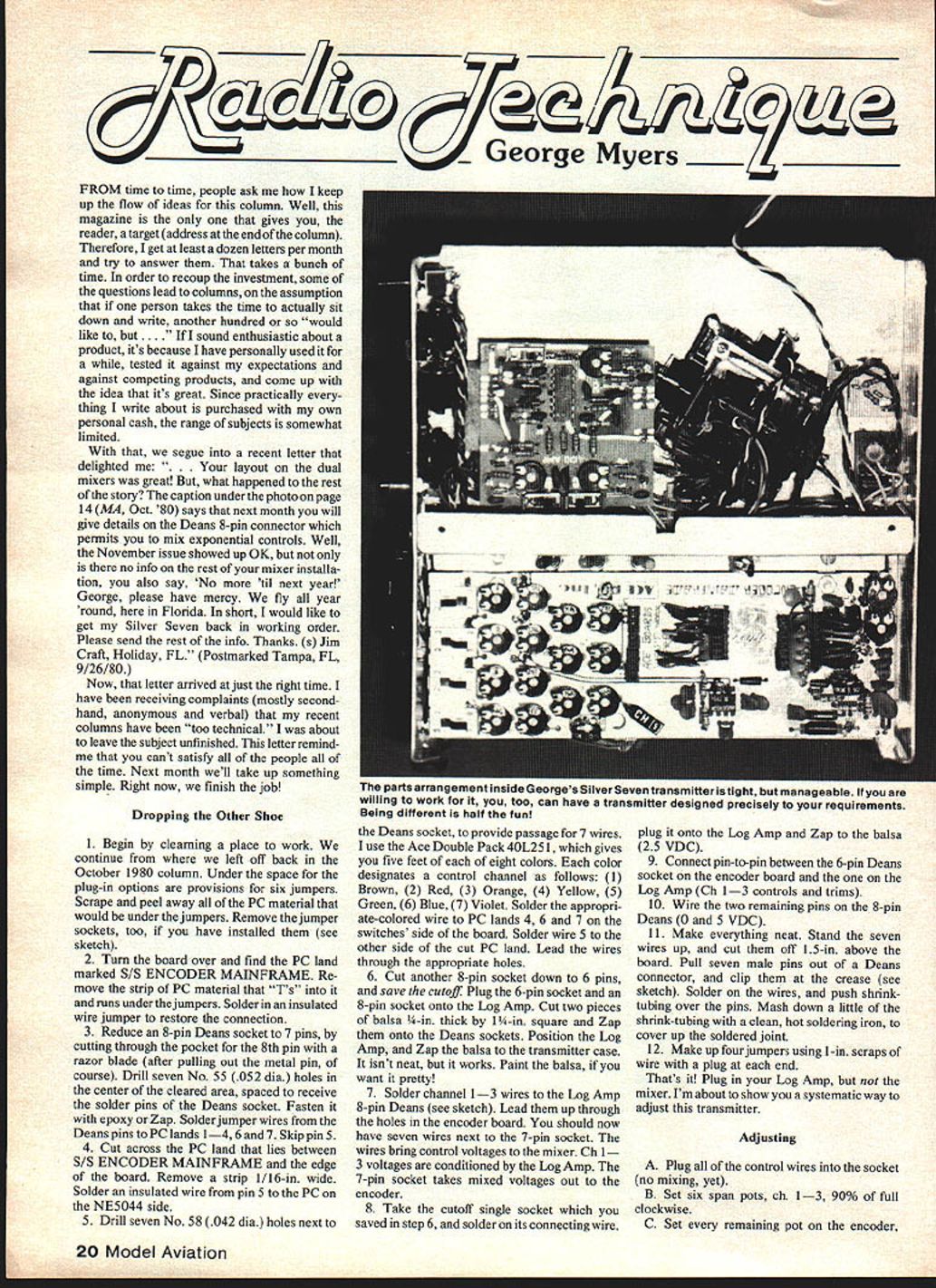
- Begin by clearing a place to work. We continue from where we left off back in the October 1980 column. Under the space for the plug-in options are provisions for six jumpers. Scrape and peel away all of the PC material that would be under the jumpers. Remove the jumper sockets, too, if you have installed them.
- Turn the board over and find the PC land marked S/S ENCODER MAINFRAME. Remove the strip of PC material that "T"s into it and runs under the jumpers. Solder in an insulated wire jumper to restore the connection.
- Reduce an 8-pin Deans socket to 7 pins by cutting through the pocket for the 8th pin with a razor blade (after pulling out the metal pin, of course). Drill seven No. 55 (.052 in. dia.) holes in the center of the cleared area, spaced to receive the solder pins of the Deans socket. Fasten it with epoxy or Zap. Solder jumper wires from the Deans pins to PC lands 1, 4, 6 and 7. Skip pin 5.
- Cut across the PC land that lies between S/S ENCODER MAINFRAME and the edge of the board. Remove a strip 1/16 in. wide. Solder an insulated wire from pin 5 to the PC on the NE5044 side.
- Drill seven No. 58 (.042 in. dia.) holes next to the Deans socket to provide passage for seven wires. I use the Ace Double Pack 40L251, which gives you five feet of each of eight colors. Each color designates a control channel as follows:
- Brown
- Red
- Orange
- Yellow
- Green
- Blue
- Violet
Solder the appropriate-colored wire to PC lands 4, 6 and 7 on the switches side of the board. Solder wire 5 to the other side of the PC land. Lead the wires through the appropriate holes.
- Cut another 8-pin socket down to 6 pins, and save the cutoff. Plug the 6-pin socket and an 8-pin socket onto the Log Amp. Cut two pieces of balsa 1/4 in. thick by 1 in. square and Zap them onto the Deans sockets. Position the Log Amp and Zap the balsa to the transmitter case. It isn't neat, but it works. Paint the balsa, if you want it pretty!
- Solder channel 1–3 wires to the Log Amp 8-pin Deans. Lead them up through the holes in the encoder board. You should now have seven wires next to the 7-pin socket. The wires bring control voltages to the mixer. Channel 1–3 voltages are conditioned by the Log Amp. The 7-pin socket takes mixed voltages out to the encoder.
- Take the cutoff single socket which you saved in step 6, and solder on its connecting wire. Plug it onto the Log Amp and Zap to the balsa (2.5 VDC).
- Connect pin-to-pin between the 6-pin Deans socket on the encoder board and the one on the Log Amp (Ch 1–3 controls and trims).
- Wire the two remaining pins on the 8-pin Deans (0 and 5 VDC).
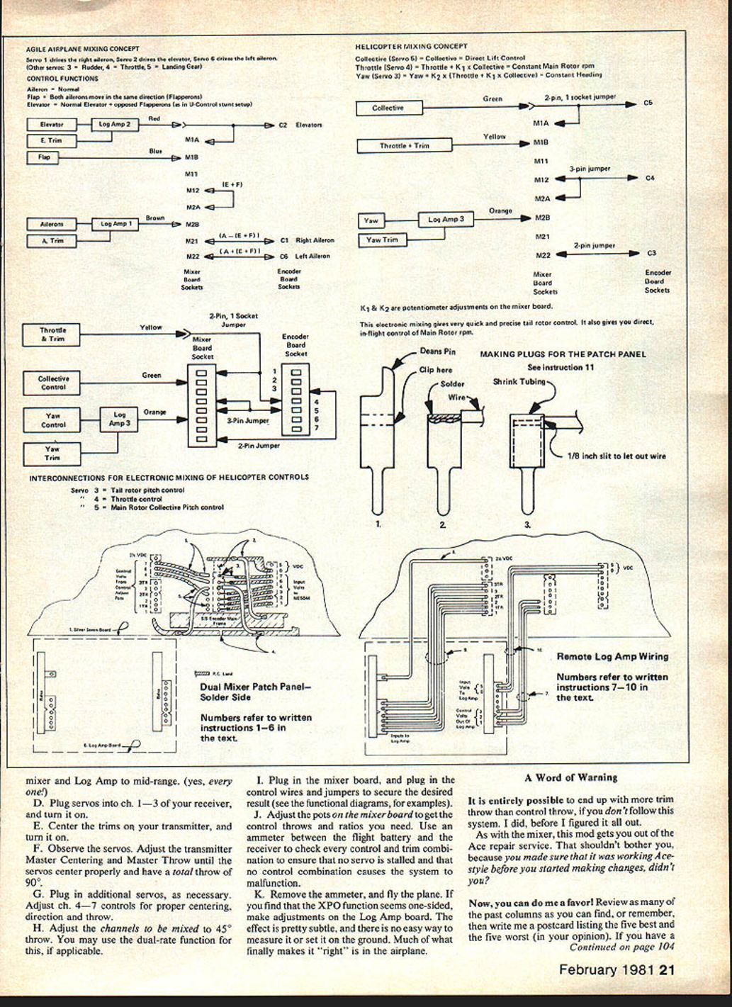
- Make everything neat. Stand the seven wires up, and cut them off 1.5 in. above the board. Pull seven male pins out of a Deans connector, and clip them at the crease. Solder on the wires, and push shrink-tubing over the pins. Mash down a little of the shrink-tubing with a clean, hot soldering iron to cover up the soldered joint.
- Make up four jumpers using 1 in. scraps of wire with a plug at each end.
That's it! Plug in your Log Amp, but not the mixer. I'm about to show you a systematic way to adjust this transmitter.
Adjusting
- Plug all of the control wires into the socket (no mixing yet).
- Set six span pots, ch. 1–3, to 90% of full clockwise.
- Set every remaining pot on the encoder. Set the mixer and Log Amp to mid-range (yes, every one).
- Plug servos into ch. 1–3 of your receiver, and turn it on.
- Center the trims on your transmitter, and turn it on.
- Observe the servos. Adjust the transmitter Master Centering and Master Throw until the servos center properly and have a total throw of 90°.
- Plug in additional servos, as necessary. Adjust ch. 4–7 controls for proper centering, direction and throw.
- Adjust the channels to be mixed to 45° throw. You may use the dual-rate function for this, if applicable.
- Plug in the mixer board, and plug in the control wires and jumpers to secure the desired result (see the functional diagrams in the original article for examples).
- Adjust the pots on the mixer board to get the control throws and ratios you need. Use an ammeter between the flight battery and the receiver to check every control and trim combination to ensure that no servo is stalled and that no control combination causes the system to malfunction.
- Remove the ammeter, and fly the plane. If you find that the XPO function seems one-sided, make adjustments on the Log Amp board. The effect is pretty subtle, and there is no easy way to measure it or to set it on the ground. Much of what finally makes it "right" is in the airplane.
A Word of Warning
It is entirely possible to end up with more trim throw than control throw if you don't follow this system. I did, before I figured it all out. As with the mixer, this mod gets you out of the Ace repair service. That shouldn't bother you, because you made sure that it was working Ace-style before you started making changes, didn't you?
Now, you can do me a favor! Review as many of the past columns as you can find, or remember, then write me a postcard listing the five best and the five worst (in your opinion). If you have a subject that hasn't been covered to your satisfaction, let me know. The baseline is that I get paid only for writing the column. The research and testing comes as a result of my interest in the subject; the expenses come out of my pocket. If I don't have an interest in your subject that predisposes me to spend money on it, there isn't much chance that I'll write about it.
I try each month to be entertaining, informative and, above all, accurate. My profession is management of Structural Test Engineering, where our motto is: "Get the right information on purpose!" It carries over into the column, too.
George M. Myers 70 Froehlich Farm Rd. Hicksville, NY 11801
Transcribed from original scans by AI. Minor OCR errors may remain.

