
Radio Technique
George Myers
Introduction
How many times have you had that feeling, during a split-S or pullout from a high-speed dive, that the elevator just wasn't doing its job? It kind of gets you in the throat, doesn't it? Let's take a look at what's happening.
Airspeed is high because engine power and gravity are working together. The airplane is flying nose-high through the air because you've got the elevator full UP. Air approaches the wing leading edge from below and is turned by the wing so that it leaves the wing going down (downwash). Thus the air approaches the horizontal tail from above, giving the tail an angle of attack. This angle adds to the elevator deflection angle, which helps the pullout. The elevator servo, however, has to work harder to reach the commanded position.
Just how much can you expect from your servo, and is it enough? Measure it or calculate it. I'll show you how.
Measuring Servo Output (The Gallon-Jug Test)
You can measure the static torque your servo can produce with an RC system and a gallon jug.
Setup
- Put a hook in the output wheel of your servo.
- Lay the servo on its side at the edge of a table (or other suitable support).
- Hook the servo to your receiver and battery pack.
Procedure
- With the hook set below center, add some water to the jug.
- Activate the system to lift the jug.
- If the hook hole rises above horizontal, let the jug down and add more water.
- Repeat steps 2 and 3 until the hole in the wheel that supports the hook stops at the horizontal position.
- Weigh the jug of water (a baby scale works well).
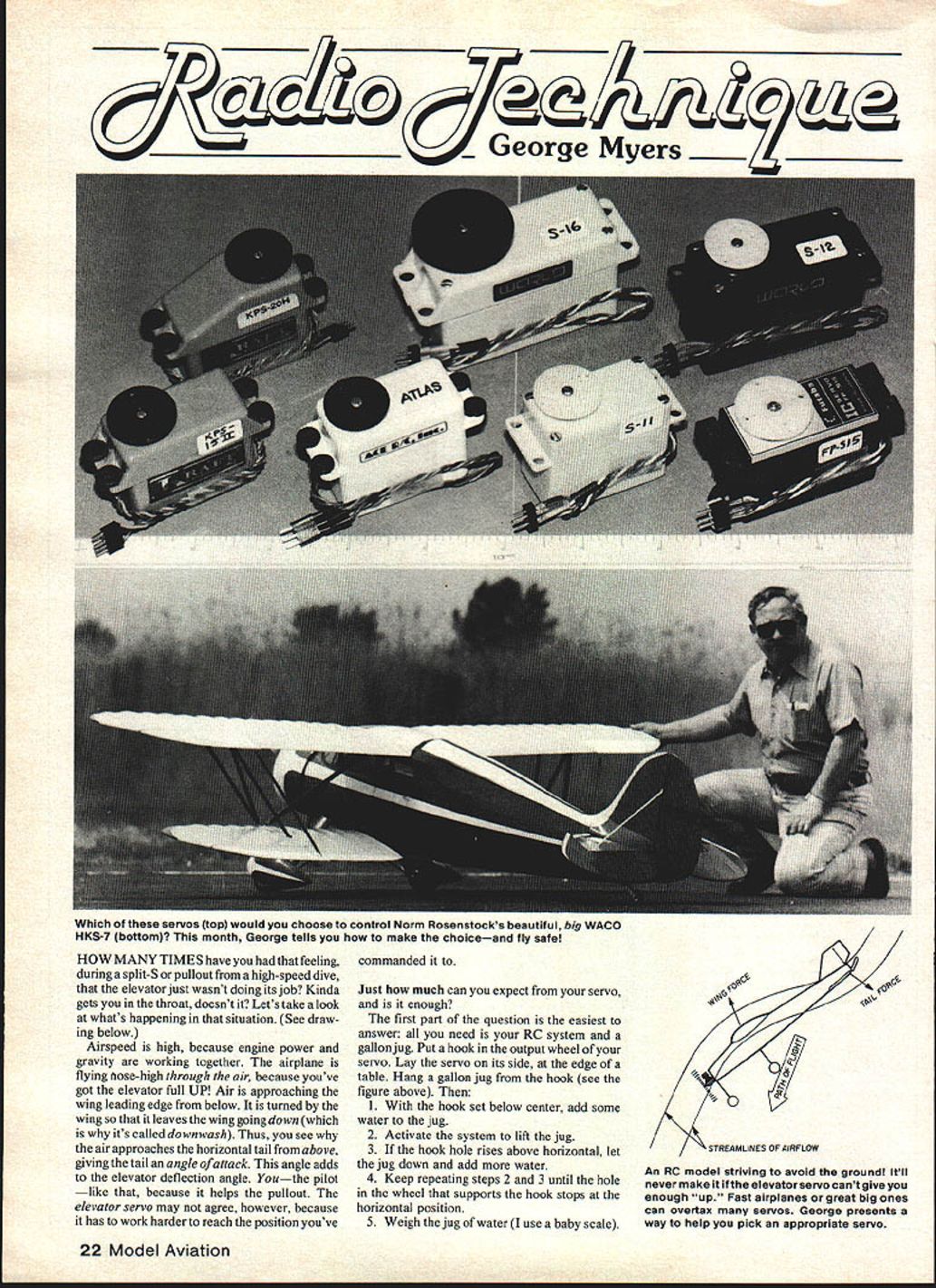
An RC model striving to avoid the ground will never make it if the elevator servo can't give you enough "up." Fast airplanes or very large ones can overtax many servos. Use this test to help pick an appropriate servo.
The Two-Wire Method for Finding Distance Between Two Holes
You need the moment arm (radius) to convert the measured weight into torque.
- Insert two wires in the servo output disk at opposite ends of a diameter.
- Measure the distance across the two wires (dia. over two wires).
- Measure the diameter of one wire.
Compute the radius: radius = [(dia. over two wires) - (dia. of one wire)] / 2
Convert the measured weight of water into torque: torque (in inch-ounces) = (weight of jug in pounds) × 16 (oz per lb) × radius (inches) (Servo torques are commonly given in inch-ounces.)
Calculating Dive Speed and Required Servo Torque
We address two questions:
- How fast will the model go?
- How strong must the servo be?
Estimating Dive Speed
Assume the model's fastest speed occurs in a dive. Measure the fuselage cross-sectional area at its maximum and add areas of exposed components (cylinder head, muffler/header, landing gear). Add the projected area of wings and tails as seen in the direction of travel if appropriate. Compute Q = Force / Area by dividing the model's takeoff weight (force) by the area calculated. Use Q to read miles-per-hour from the relevant graph (graph not included here). Note: dive speed can be affected by propeller pitch and engine rpm; "propeller stopped" is an average assumption.
Control Surface Hinge Torque Equation
Start with the control surface hinge torque equation:
T = V^2 × S × C × F
where:
- T = hinge torque (in.-oz. when converted appropriately)
- V = estimated dive speed (mph)
- S = control surface area (square inches). If two surfaces are driven by one servo, measure both.
- C = geometric average chord of the control surface (inches). If unsure, use the maximum chord (conservative).
- F = an empirical function of angle (see below)
- D = control surface deflection angle (degrees)
- A = downwash angle on the tail (degrees), typically about 5°
To convert the hinge torque into required servo torque, multiply by the ratio of servo wheel (or arm) radius to control horn radius, and include a geometric factor for servo motion. Because servo radius at full UP is 0.707 × the measured radius (for 90° motion), the working conversion is approximately:
STR = (0.707 × L1 / L2) × V^2 × S × C × F (in.-oz.)
where:
- STR = servo torque required (in.-oz.)
- L1 = servo arm or wheel radius (inches)
- L2 = control horn radius or equivalent moment arm at the elevator (inches)
Empirical Function F
F is an empirical function of (A + D). Use the following values for F in your calculations (A + D in degrees):
- (A + D) = 10° → F = 0.000042
- (A + D) = 15° → F = 0.000055
- (A + D) = 20° → F = 0.000045
- (A + D) = 25° → F = 0.0000588 (value used in the sample problem)
- (A + D) = 30° → F = 0.000063
A is the downwash angle (about 5°); choose D accordingly.
Sample Problem: Curare Elevator
- Find dive speed and Q.
- Takeoff weight = 9.75 lb (full tank)
- Projected cross-section areas (gear retracted), square inches:
- Fuselage: 17.0
- Cylinder head: 2.6
- Header: 2.4
- Tuned pipe: 4.5
- Propeller: 1.5
- Total: 28.0 sq. in.
- Q = 9.75 / 28 = 0.348 lb/sq. in.
- Vdive = 130 mph (from graph, propeller stopped)
Note: Dive speed can be less than, equal to, or greater than the graph value, depending on propeller pitch and rpm.
- Find servo torque required.
(Note: Use Fourmost Racing Products Gapless Hinge or similar; set D = 20°, A ≈ 5°, so (D + A) = 25° → F = 0.0000588.)
a. Elevator parameters
- Span = 24 in.
- Chord = C = 2 in.
- Area = S = 48 sq. in.
- V = 130 mph
- (D + A) = 25° → F = 0.0000588
b. Elevator hinge torque T = V^2 × S × C × F = 130^2 × 48 × 2 × 0.0000588 = 95.5 in.-oz.
- Select a servo and compare.
Try the Ace R/C "Atlas":
- Output wheel radius L1 = 0.325 in.
- Stroke = 0.460 in. → half-stroke J = 0.230 in.
- Effective control horn radius (approx.) L2 ≈ 0.672 in. (from geometry: J = L1 × sin D etc.)
- Conversion factor = (0.7 × L1 / L2) = (0.7 × 0.325 / 0.672) = 0.339
- Servo torque required = 0.339 × 95.5 = 32.3 in.-oz.
- Servo torque available (Atlas) = 45.5 in.-oz. → Atlas OK!
Note: People sometimes get away with small servos by using small deflection angles and avoiding aggressive maneuvers. This static analysis does not include shock and vibration factors, which can increase servo requirements by factors of four or more.
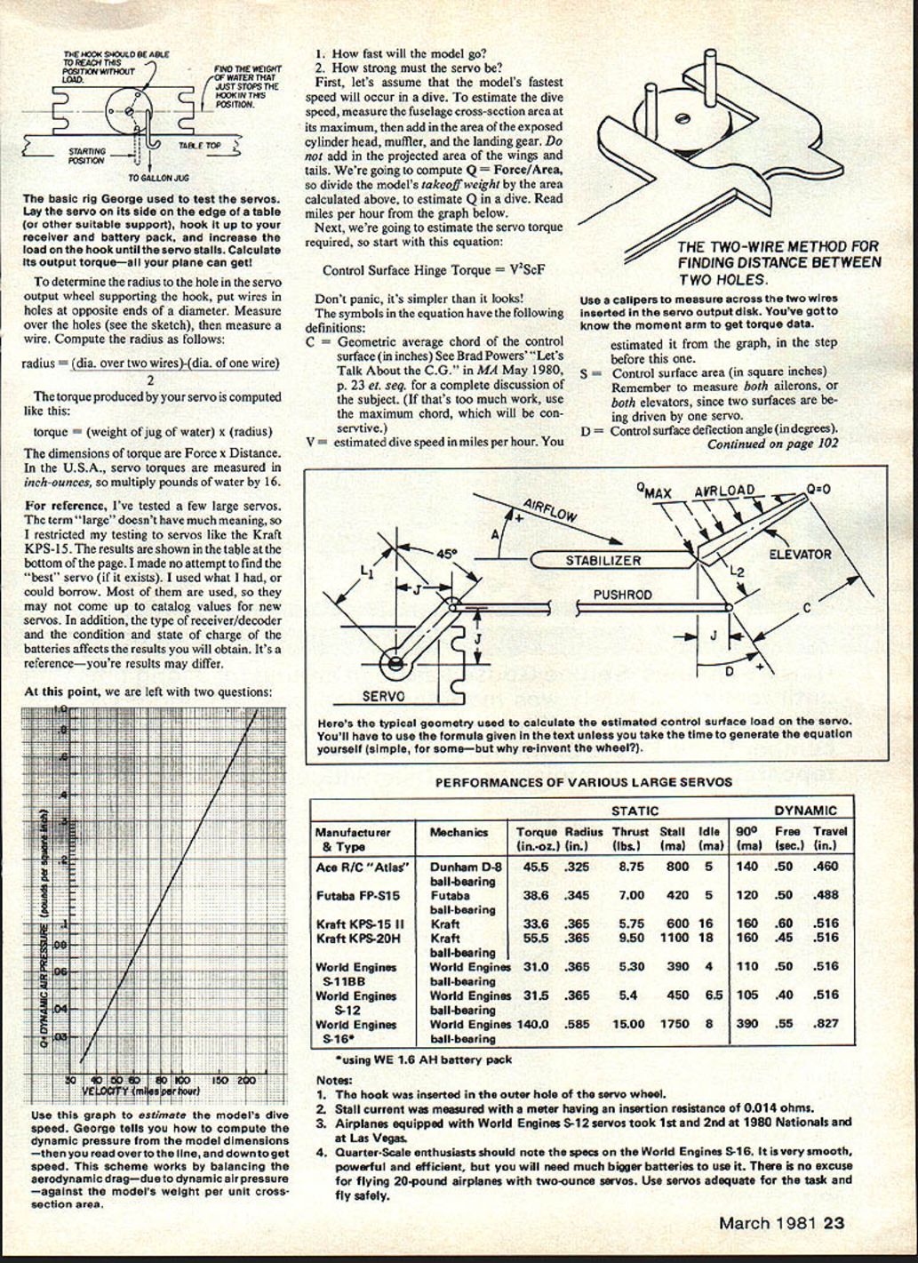
Performances of Various Large Servos
(Values measured; may differ from catalog values. Results depend on receiver/decoder type, servo condition, battery state of charge, etc.)
- Ace R/C "Atlas" — Dunham D-8 ball-bearing
- Torque: 45.5 in.-oz.
- Radius: 0.325 in.
- Thrust: 8.75 lbs.
- Stall current: 800 mA
- Idle: 5 mA
- 90°: 140 mA
- Free (sec): 0.50
- Travel (in.): 0.460
- Futaba FP-S15 — Futaba ball-bearing
- Torque: 38.6 in.-oz.
- Radius: 0.345 in.
- Thrust: 7.00 lbs.
- Stall: 420 mA
- Idle: 5 mA
- 90°: 120 mA
- Free (sec): 0.50
- Travel (in.): 0.488
- Kraft KPS-15 II — Kraft
- Torque: 33.6 in.-oz.
- Radius: 0.365 in.
- Thrust: 5.75 lbs.
- Stall: 600 mA
- Idle: 16 mA
- 90°: 160 mA
- Free (sec): 0.60
- Travel (in.): 0.516
- Kraft KPS-20H — Kraft
- Torque: 55.5 in.-oz.
- Radius: 0.365 in.
- Thrust: 9.50 lbs.
- Stall: 1100 mA
- Idle: 18 mA
- 90°: 160 mA
- Free (sec): 0.45
- Travel (in.): 0.516
- World Engines S-11BB — World Engines ball-bearing
- Torque: 31.0 in.-oz.
- Radius: 0.365 in.
- Thrust: 5.30 lbs.
- Stall: 390 mA
- Idle: 4 mA
- 90°: 110 mA
- Free (sec): 0.50
- Travel (in.): 0.516
- World Engines S-12 — World Engines ball-bearing
- Torque: 31.5 in.-oz.
- Radius: 0.365 in.
- Thrust: 5.4 lbs.
- Stall: 450 mA
- Idle: 6.5 mA
- 90°: 105 mA
- Free (sec): 0.40
- Travel (in.): 0.516
- World Engines S-16* — World Engines ball-bearing
- Torque: 140.0 in.-oz.
- Radius: 0.585 in.
- Thrust: 15.00 lbs.
- Stall: 1750 mA
- Idle: 8 mA
- 90°: 390 mA
- Free (sec): 0.55
- Travel (in.): 0.827
*Using WE 1.6 AH battery pack.
Notes
- The hook was inserted in the outer hole of the servo wheel.
- Stall current was measured with a meter having an insertion resistance of 0.014 ohms.
- Airplanes equipped with World Engines S-12 servos took 1st and 2nd at the 1980 Nationals and at Las Vegas.
- Quarter-scale enthusiasts should note the specs on the World Engines S-16. It is very smooth, powerful and efficient, but you will need much bigger batteries to use it. There is no excuse for flying 20-pound airplanes with two-ounce servos. Use servos adequate for the task and fly safely.
Closing
Now you can see how to measure servo torque and estimate required servo size for control surfaces in high-speed dives. Shock and vibration factors, pushrod strength, and battery sizing will be covered in a follow-up. Keep the letters flowing!
George M. Myers 70 Froehlich Farm Rd., Hicksville, NY 11801.
Transcribed from original scans by AI. Minor OCR errors may remain.

