
Radio Technique
George Myers
Loads on Your Servos
LAST month, we gave you a parametric equation for picking the size servo you need. It was based on the usual aileron or elevator situation, in which a tapered wood strip is attached to the trailing edge of a wing or stabilizer by some kind of hinge in the gap. This month we will extend the discussion into mass- and aerodynamically-balanced surfaces, with some discussion of dynamics. First, let's look at various kinds of servo loads.
Static overloads
The throttle is the control that should be least likely to damage a servo, yet (due to carelessness) it most frequently is the one that eats them! The cause is simply that the owner doesn't test his setup carefully enough before committing it to service. The test is ridiculously easy. Set High motor plus High trim. Disconnect the clevis at the throttle. Push the throttle arm. It should be free to go a little farther in the High direction. Go to Low motor plus Low trim. The throttle arm should have a little more freedom in that direction, too. Now hook it up and go flying!
Shock
No one can calculate the shock that results from your nose gear dropping into a gopher hole. The standard approach is to isolate the servo behind a spring or a spongy pushrod, so that the servo has enough control to steer the plane, but is protected from shock damage. You work up to the answer by starting with a weak spring, then cutting off one coil at a time until it's stiff enough.
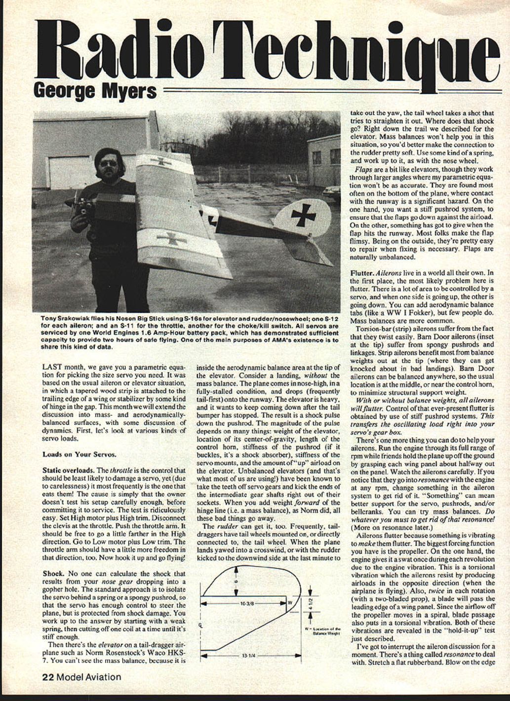
Then there's the elevator on a tail-dragger airplane such as Norm Rosenstock's Waco HKS-7. You can't see the mass balance, because it is inside the aerodynamic balance area at the tip of the elevator. Consider a landing, without the mass balance. The plane comes in nose-high, in a fully-stalled condition, and drops (frequently tail-first) onto the runway. The elevator is heavy, and it wants to keep coming down after the tail bumper has stopped. The result is a shock pulse down the pushrod. The magnitude of the pulse depends on many things: weight of the elevator, location of its center-of-gravity, length of the control horn, stiffness of the pushrod (if it buckles, it's a shock absorber), stiffness of the servo mounts, and the amount of "up" airload on the elevator. Unbalanced elevators (and that's what most of us are using) have been known to take the teeth off servo gears and kick the ends of the intermediate gear shafts right out of their sockets. When you add weight forward of the hinge line (i.e. a mass balance), as Norm did, all these bad things go away.
The rudder can get it, too. Frequently, taildraggers have tail wheels mounted on, or directly connected to, the rudder. When the plane lands yawed into a crosswind, or with the rudder kicked to the downwind side at the last minute to take out the yaw, the tail wheel takes a shot that tries to straighten it out. Where does that shock go? Right down the trail we described for the elevator. Mass balances won't help you in this situation, so you'd better make the connection to the rudder pretty soft. Use some kind of a spring, and work up to it, as with the nose wheel.
Flaps are a bit like elevators, though they work through larger angles where my parametric equation won't be as accurate. They are found most often on the bottom of the plane, where contact with the runway is a significant hazard. On the one hand, you want a stiff pushrod system, to ensure that the flaps go down against the airload. On the other, something has got to give when the flap hits the runway. Most folks make the flap flimsy. Being on the outside, they're pretty easy to repair when fixing is necessary. Flaps are naturally unbalanced.
Flutter
Ailerons live in a world all their own. In the first place, the most likely problem here is flutter. There is a lot of area to be controlled by a servo, and when one side is going up, the other is going down. You can add aerodynamic balance tabs (like a WW I Fokker), but few people do. Mass balances are more common.
Torsion-bar (strip) ailerons suffer from the fact that they twist easily. Barn Door ailerons (inset at the tip) suffer from spongy pushrods and linkages. Strip ailerons benefit most from balance weights out at the tip (where they can get knocked about in bad landings). Barn Door ailerons can be balanced anywhere, so the usual location is at the middle, or near the control horn, to minimize structural support weight. With or without balance weights, all ailerons will flutter. Control of that ever-present flutter is obtained by use of stiff pushrod systems. This transfers the oscillating load right into your servo's gear box.
There's one more thing you can do to help your ailerons. Run the engine through its full range of rpm while friends hold the plane up off the ground by grasping each wing panel about halfway out on the panel. Watch the ailerons carefully. If you notice that they go into resonance with the engine at any rpm, change something in the aileron system to get rid of it. "Something" can mean better support for the servo, pushrods and/or bellcranks. You can try mass balances. Do whatever you must to get rid of that resonance! (More on resonance later.)
Ailerons flutter because something is vibrating to make them flutter. The biggest forcing function you have is the propeller. On the one hand, the engine gives it a swat once during each revolution due to the engine vibration. This is a torsional vibration which the ailerons resist by producing airloads in the opposite direction (when the airplane is flying). Also, twice in each revolution (with a two-bladed prop), a blade will pass the leading edge of a wing panel. Since the airflow off the propeller is in a spiral, blade passage also puts in a torsional vibration. Both of these vibrations are revealed in the "hold-it-up" test we just described.
I've got to interrupt the aileron discussion for a moment. There's a thing called resonance to deal with. Stretch a flat rubberband. Blow on the edge of the rubber, near the middle of the stretched length. You see the effect of resonance. The force your breath puts on the rubberband is small, but the response is large. Pull down on the rubberband, and you'll get an idea how large it is. Go outside where the wind is blowing, and you may see a rubberband that is stretched 12 inches vibrating through an arc of three inches!
What do we do about it?
Take a ruler out of your desk. Blow on its edge. Not much happens, right? Stiffness helps. So does added weight. The trouble with weight is that it interferes with flying. So we'd better stick to stiffness when we de-resonate our model.
Now, back to the aileron. Another forcing function is called "vortex shedding." This one is a result of the properties of air and the shape of the wing and aileron. The best example I can give is the famous movie of "Galloping Gertie," the bridge that shook itself down in torsional resonance. The bridge acted exactly as did the rubberband when you blew on it. Your ailerons will do it too, whenever airspeed gets high enough. The forcing function is always there, waiting to destroy your airplane. You minimize it by sealing the gap between wing and aileron, balancing the aileron on its hinge with overhanging weights, and by keeping the servo drive system as stiff as possible.
Choose a Servo!
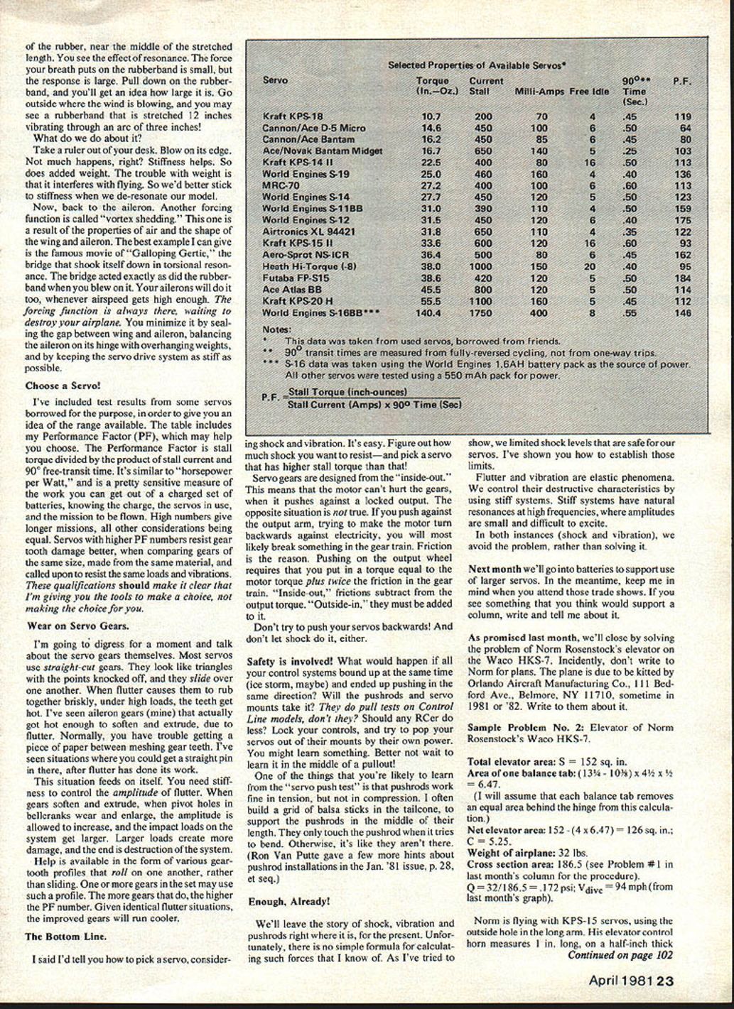
I've included test results from some servos borrowed for the purpose, in order to give you an idea of the range available. The table includes my Performance Factor (PF), which may help you choose. The Performance Factor is stall torque divided by the product of stall current and 90° free-transit time. It's similar to "horsepower per Watt," and is a pretty sensitive measure of the work you can get out of a charged set of batteries. The numbers are from the mission to be flown. High numbers give longer missions, all other considerations being equal. Servos with higher PF numbers resist gear tooth damage better, when comparing gears of the same size, made from the same material, and called upon to resist the same loads and vibrations. These qualifications should make it clear that I'm giving you the tools to make a choice, not making the choice for you.
Wear on Servo Gears
I'm going to digress for a moment and talk about the servo gears themselves. Most servos use straight-cut gears. They look like triangles with the points knocked off, and they slide over one another. When flutter causes them to rub together briskly, under high loads, the teeth get hot. I've seen aileron gears (mine) that actually got hot enough to soften and extrude, due to flutter. Normally, you have trouble getting a piece of paper between meshing gear teeth. I've seen situations where you could get a straight pin in there, after flutter has done its work.
This situation feeds on itself. You need stiffness to control the amplitude of flutter. When gears soften and extrude, when pivot holes in bellcranks wear and enlarge, the amplitude is allowed to increase, and the impact loads on the system get larger. Larger loads create more damage, and the end is destruction of the system. Help is available in the form of various gear-tooth profiles that roll on one another, rather than sliding. One or more gears in the set may use such a profile. The more gears that do, the higher the PF number. Given identical flutter situations, the improved gears will run cooler.
The Bottom Line
I said I'd tell you how to pick a servo, considering shock and vibration. It's easy. Figure out how much shock you want to resist—and pick a servo that has higher stall torque than that!
Servo gears are designed from the "inside-out." This means that the motor can't hurt the gears, when it pushes against a locked output. The opposite situation is not true. If you push against the output arm, trying to make the motor turn backwards against electricity, you will most likely break something in the gear train. Friction is the reason. Pushing on the output wheel requires that you put in a torque equal to the motor torque plus twice the friction in the gear train. "Inside-out," frictions subtract from the output torque. "Outside-in," they must be added to it.
Don't try to push your servos backwards! And don't let shock do it, either.
Safety is involved! What would happen if all your control systems bound up at the same time (ice storm, maybe) and ended up pushing in the same direction? Will the pushrods and servo mounts take it? They do pull tests on Control Line models, don't they? Should any R/Cer do less? Lock your controls, and try to pop your servos out of their mounts by their own power. You might learn something. Better not wait to learn it in the middle of a pullout!
One of the things that you're likely to learn from the "servo push test" is that pushrods work fine in tension, but not in compression. I often build a grid of balsa sticks in the tailcone, to support the pushrods in the middle of their length. Then only the portion from the support on out tries to bend. Otherwise, it's like they aren't there. (Ron Van Putte gave a few more hints about pushrod installations in the Jan. '81 issue, p. 28, see rpt.)
Enough, Already!
We'll leave the story of shock, vibration and pushrods right where it is, for the present. Unfortunately, there is no simple formula for calculating such forces that I know of. As I've tried to show, we limit shock levels that are safe for our servos. I've shown you how to establish those limits.
Flutter and vibration are elastic phenomena. We can control their destructive characteristics by using stiff systems. Stiff systems have natural resonances at high frequencies, where amplitudes are small and difficult to excite.
In both instances (shock and vibration), we avoid the problem, rather than solving it.
Next month we'll go into batteries to support use of larger servos. In the meantime, keep me in mind when you attend those trade shows. If you see something that you think would support a column, write and tell me about it.
As promised last month, we'll close by solving the problem of Norm Rosenstock's elevator on the Waco HKS-7. Incidentally, don't write to Norm for plans. The plane is due to be kitted by Orlando Aircraft Manufacturing Co., 111 Bedford Ave., Belmore, NY 11710, sometime in 1981 or '82. Write to them about it.
Selected Properties of Available Servos*
- Note: This data was taken from used servos, borrowed from friends. 90° transit times are measured from fully-reversed cycling, not from one-way trips. S-16 data was taken using the World Engines 1.6AH battery pack as the source of power. All other servos were tested using a 550 mAh pack for power.
- Kraft KPS-18
- Torque: 10.7 in.-oz.
- Stall current: 200 mA
- Free/idle: 70 mA
- Test value: 4
- 90° time: 0.45 s
- P.F.: 119
- Cannon/Ace D-5 Micro
- Torque: 14.6 in.-oz.
- Stall current: 450 mA
- Free/idle: 100 mA
- Test value: 6
- 90° time: 0.50 s
- P.F.: 64
- Cannon/Ace Bantam
- Torque: 16.2 in.-oz.
- Stall current: 450 mA
- Free/idle: 85 mA
- Test value: 6
- 90° time: 0.45 s
- P.F.: 80
- Ace/Novak Bantam Midget
- Torque: 16.7 in.-oz.
- Stall current: 650 mA
- Free/idle: 140 mA
- Test value: 5
- 90° time: 0.25 s
- P.F.: 103
- Kraft KPS-14 II
- Torque: 22.5 in.-oz.
- Stall current: 400 mA
- Free/idle: 80 mA
- Test value: 16
- 90° time: 0.50 s
- P.F.: 113
- World Engines S-19
- Torque: 25.0 in.-oz.
- Stall current: 460 mA
- Free/idle: 160 mA
- Test value: 4
- 90° time: 0.40 s
- P.F.: 136
- MRC-70
- Torque: 27.2 in.-oz.
- Stall current: 400 mA
- Free/idle: 100 mA
- Test value: 6
- 90° time: 0.60 s
- P.F.: 123
- World Engines S-14
- Torque: 27.7 in.-oz.
- Stall current: 450 mA
- Free/idle: 120 mA
- Test value: 6
- 90° time: 0.50 s
- P.F.: 123
- World Engines S-11BB
- Torque: 31.0 in.-oz.
- Stall current: 390 mA
- Free/idle: 110 mA
- Test value: 4
- 90° time: 0.50 s
- P.F.: 159
- World Engines S-12
- Torque: 31.5 in.-oz.
- Stall current: 450 mA
- Free/idle: 120 mA
- Test value: 6
- 90° time: 0.40 s
- P.F.: 175
- Airtronics XL 94421
- Torque: 31.8 in.-oz.
- Stall current: 650 mA
- Free/idle: 110 mA
- Test value: 4
- 90° time: 0.35 s
- P.F.: 122
- Kraft KPS-15 II
- Torque: 33.6 in.-oz.
- Stall current: 600 mA
- Free/idle: 120 mA
- Test value: 16
- 90° time: 0.60 s
- P.F.: 93
- Aero-Sport NS-ICR
- Torque: 36.4 in.-oz.
- Stall current: 500 mA
- Free/idle: 80 mA
- Test value: 6
- 90° time: 0.45 s
- P.F.: 162
- Heath Hi-Torque (-8)
- Torque: 38.0 in.-oz.
- Stall current: 1000 mA
- Free/idle: 150 mA
- Test value: 20
- 90° time: 0.40 s
- P.F.: 95
- Futaba FP-S15
- Torque: 38.6 in.-oz.
- Stall current: 420 mA
- Free/idle: 120 mA
- Test value: 5
- 90° time: 0.50 s
- P.F.: 184
- Ace Actas BB
- Torque: 45.5 in.-oz.
- Stall current: 800 mA
- Free/idle: 120 mA
- Test value: 8
- 90° time: 0.50 s
- P.F.: 114
- Kraft KPS-20 H
- Torque: 55.5 in.-oz.
- Stall current: 1100 mA
- Free/idle: 160 mA
- Test value: 5
- 90° time: 0.45 s
- P.F.: 112
- World Engines S-16BB***
- Torque: 140.4 in.-oz.
- Stall current: 1750 mA
- Free/idle: 400 mA
- Test value: 8
- 90° time: 0.55 s
- P.F.: 146
Notes:
- * This data was taken from used servos, borrowed from friends.
- ** 90° transit times are measured from fully-reversed cycling, not from one-way trips.
- *** S-16 data was taken using the World Engines 1.6AH battery pack as the source of power. All other servos were tested using a 550 mAh pack for power.
P.F. (Performance Factor) calculation:
- P.F. = Stall Torque (inch-ounces) / (Stall Current (Amps) × 90° Time (sec))
Sample Problem No. 2: Elevator of Norm Rosenstock's Waco HKS-7
- Total elevator area: S = 152 sq. in.
- Area of one balance tab: (13 3/4 - 10 3/8) × 4 1/2 = 6.47.
- (I will assume that each balance tab removes an equal area behind the hinge from this calculation.)
- Net elevator area: 152 − (4 × 6.47) = 126.1 sq. in.; C = 0.525.
- Weight of airplane: 32 lbs.
- Cross section area: 186.5 (see Problem #1 in last month's column for the procedure).
- Q = 32 / 186.5 = 0.172 psi; V^2 = 94 mph (from last month's graph).
Norm is flying with KPS-15 servos, using the outside hole in the long arm. His elevator control horn measures 1 in. long, on a half-inch thick elevator. Therefore:
- L1 = 0.525; J = 0.371; L2 = 1.25; D = sin^-1(0.371 / 1.25) = 17.26°.
Servo torque required:
- T = 0.7 × L1 × V^2 × S × C × F (where F = 0.00005 from last month's chart).
- T = 0.371 × 94 × 94 × 126 × 5.25 × 0.00005 = 86.7 in.-oz.
Better use a World Engines S-16, Norm!
George M. Myers 70 Froehlich Farm Road Hicksville, NY 11801
Transcribed from original scans by AI. Minor OCR errors may remain.

