
Radio Technique
George M. Myers
An electronic stopwatch
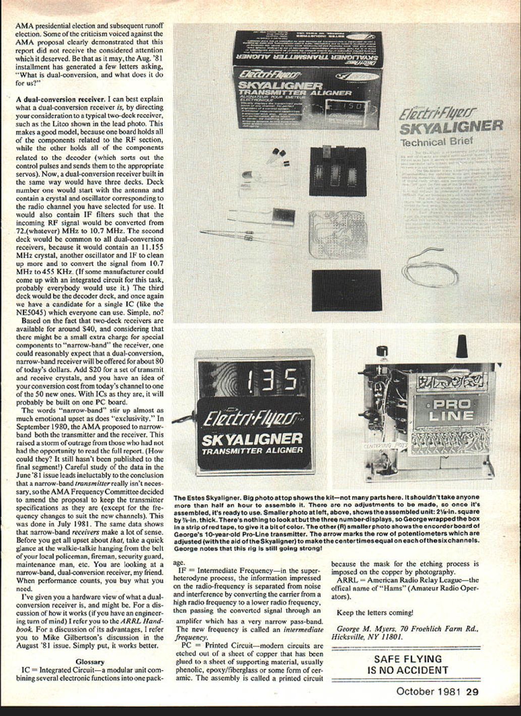
The Estes Skyaligner is subtitled "Transmitter Aligner," which might lead you to expect that it somehow plugs into your transmitter. It doesn't. You plug the Skyaligner into your receiver, in place of a servo. While there, the Skyaligner is powered by your flight pack and it measures the ON time of the control pulse that the servo would have received. The usual range of numbers displayed is from 1.00 to 2.00, which you interpret as milliseconds (0.00100 to 0.00200 sec).
I enjoy building electronic kits, but this one went together so fast I hardly noticed doing it. Anyone could assemble it in 30 minutes, including the time spent reading the instructions and checking the parts. It worked properly the first time it was plugged in. There's nothing to adjust — all you can do is plug it in and read it. Current consumption is about 80 mA, which mostly goes to light the display.
Using the Skyaligner
As the Skyaligner instructions explain, plug the Skyaligner into your receiver, move from one servo position to another, and adjust the center time of each channel in the transmitter. Inside a typical 1970s transmitter (before the NE5044 chip — see "WRAM's Show — 1981" in the June '81 MA) you will find the necessary potentiometers to make these adjustments.
- Set the transmitter's potentiometers so that all channels display the same time when the controls and trims are centered. The exception is the Retract channel, which only shows separate Up and Down numbers.
- Adjust servos so they all center mechanically the same when driven by the same control pulse. Turn on the system, center the control lever and trim on one channel (for example, aileron), then plug in your servos one at a time into the receiver's aileron channel and observe how they center. Any servo that centers differently from the rest must be adjusted:
- Some servos (World Engines, Ace) are centered by inserting a screwdriver or hex wrench into the hole in the output shaft.
- Others (Kraft) are centered by moving the potentiometer inside the servo case.
- Servos with multi-spline output shafts (Airtronics, Cox/Sanwa, OS) usually have no internal provision for centering; you must place the output arm or wheel on the shaft appropriately.
Once all the servos center identically, they are truly interchangeable. Assuming the transmitter is aligned and the servos are interchangeable, you can apply the same setup to other systems you own, making component swapping much simpler.
Advanced use — super transmitters
The real payoff for the Skyaligner comes with a feature-rich transmitter (for example, my Ace Silver Seven). With it you can adjust and offset control spans, set exponential and dual rates, adjust trim authority, mix controls, etc., without reference to the airplane. The workflow is simple: measure what you've got — centers, spans, trims, mixtures — and write them down. If you want to use the equipment for something else, go through the setup again. When you want to return to a developed setup, pull out your records and the Skyaligner, and restore the transmitter in a few easy minutes.
Comparison to Ken Jesser's Digital Pulse Meter
You may ask how the Skyaligner differs from the Digital Pulse Meter designed by Ken Jesser (published in RCM and kitted by Royal Electronics). The answer: it uses slightly different components, fits in a smaller box, and is available from Estes Industries, Inc., Penrose, CO 81240. Specialty items like this are kitted in batches; if you want one, buy it when it's available because the next batch may take a long time.
What is a dual-conversion receiver?
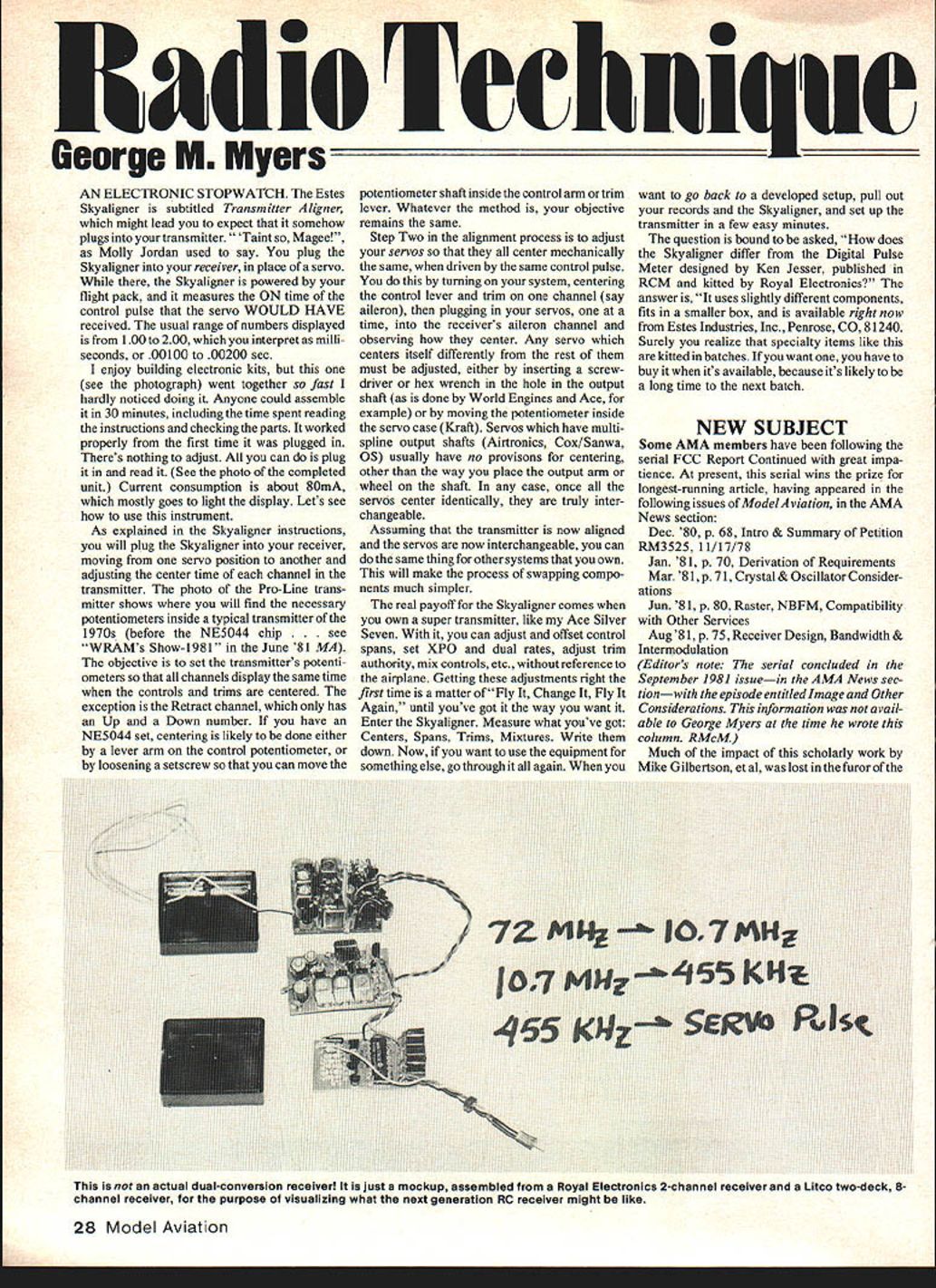
Some readers asked, "What is dual-conversion, and what does it do for us?" A good way to think of a dual-conversion receiver is to compare it to a typical two-deck receiver (such as the Litco). A two-deck receiver usually has one board for the RF section and another for the decoder. A dual-conversion receiver built in the same spirit would have three decks:
- Deck 1: Starts at the antenna, contains a crystal and oscillator for the selected radio channel, and IF filters to convert the incoming RF signal (e.g., 72.(whatever) MHz) down to 10.7 MHz.
- Deck 2: Contains an 11.155 MHz crystal, another oscillator, and IF stages to further clean the signal and convert it from 10.7 MHz down to 455 kHz. (If someone produced an integrated circuit for this task, everyone would probably use it.)
- Deck 3: The decoder deck, which could also be a candidate for a single IC solution (for example, an NE5045-type device).
Given that two-deck receivers are available for around $40, and allowing a small extra charge for special components to "narrow-band" the receiver, one could reasonably expect a dual-conversion, narrow-band receiver to be offered for about $80. Add $20 for a set of transmit and receive crystals and you have an idea of the conversion cost from today's channels to one of the new ones. With current IC technology, it will probably be built on a single PC board.
Narrow-band and exclusivity
The words "narrow-band" often stir strong reactions, similar to those around "exclusivity." In September 1980 the AMA proposed to narrow-band both the transmitter and the receiver. That proposal caused outrage from people who hadn't read the full report. Careful study of the data in the June '81 issue makes it clear that a narrow-band transmitter isn't really necessary, so the AMA Frequency Committee amended the proposal in July 1981 to keep the transmitter specifications essentially as they are (aside from frequency changes for the new channels). The same data shows that narrow-band receivers make a lot of sense.
Before you get upset, consider the walkie-talkie hanging from the belt of your local policeman, fireman, security guard, or maintenance man: you're looking at a narrow-band, dual-conversion receiver. When performance counts, you buy what you need.
For a hardware explanation of how a dual-conversion receiver is built I have given you a view here. For a detailed discussion of how it works (if you have an engineering turn of mind) see the ARRL Handbook. For advantages and practical commentary, see Mike Gilbertson's discussion in the August '81 issue. Simply put: it works better.
Glossary
- IC = Integrated Circuit — a modular unit combining several electronic functions into one package.
- IF = Intermediate Frequency — in the superheterodyne process, the information impressed on the radio-frequency carrier is separated from noise and interference by converting the carrier from a high radio frequency to a lower frequency and passing the converted signal through an amplifier with a narrow pass-band. The new frequency is called the intermediate frequency.
- PC = Printed Circuit — modern circuits are etched from a sheet of copper glued to supporting material (usually phenolic, epoxy/fiberglass, or ceramic). The assembly is called a printed circuit because the mask for the etching process is imposed on the copper by photography.
- ARRL = American Radio Relay League — the national organization of amateur radio operators ("Hams").
Keep the letters coming!
George M. Myers 70 Froehlich Farm Rd. Hicksville, NY 11801
Transcribed from original scans by AI. Minor OCR errors may remain.

