
Radio Technique
George M. Myers
"Dear George, I know a little about electronics and have access to some pretty good equipment. I'd like to do some work on my radio: make it work, add a mixer, dual rates, exponential, etc., but I can't do it because I don't have schematics and the manufacturer can't (or won't) supply me with them. Can you help me? (S) A Devoted Reader"
FIXING OLD RADIOS
Every month brings another letter like this. Sometimes (very rarely) I can lay hands on the necessary schematics. Most often I have to tell the reader what I'm about to tell you: There are too many manufacturers and too many variations of the systems offered for anyone to keep up with them. Changes are continuous and evolutionary. Each batch of servos, every new transmitter series, every change in anything causes minor changes someplace. Integrated circuits make the changes invisible (you can't see what masks are changed, or figure out why).
Ours is a volatile hobby. Someone gets a bright idea, makes a few prototypes, then commits to production of whatever lot size prudence dictates and his wallet can afford. The units get reviewed, and the reviewers find problems that the producer never anticipated. Changes are made, and the units are resubmitted for review. Eventually, they pass the reviewer's tests. Then the field reports start coming in. More changes. Production continues, and who knows where in the cycle your unit was built?
When it's time for the next lot to go into production, costs have risen, and someone has come out with a cheaper and "better" component. To keep the price constant (and still leave a profit), minor changes are made to accommodate the new item. Changes accumulate in this way until the next revolutionary change is necessary (like when we get the new frequencies). A big production run in this hobby is 5,000 units, so you can see the problem. Add to that the "need" to attract customers and thereby stay in business, and you can see the scope of the problem.
When you send an item in for repair, a manufacturer's service department will often choose simply to replace the item — like an amplifier or a servo. Batteries are replaced when there's trouble; sometimes there is no way to make a repair. Transmitters and receivers may be repaired if the fault is obvious and simple. Yet some folks repair their own RC systems.
Getting the Most From Radio Control Systems (book)
Getting the Most From Radio Control Systems Fred M. Marks Kalmbach Publishing Co., 1027 North Seventh St., Milwaukee, WI 53233
- Issue marked 12046. $8.95
Step one: buy the book. It doesn't talk you into buying — it tells you how I feel about it.
Step two: read the book cover to cover. Skim over the hard parts, mark them in the margin with a pencil, then go back and reread until you understand. I'll tell you right now: the book gives an overview of the RC system; when you've finished the book you still won't know which end of a soldering iron is hot (if you didn't know before), but you will have a pretty good idea what's inside those pretty colored boxes we lovingly call an RC system — you will have received your primary education.
Step three: make sure the troubles can be fixed. According to the failure tree (pp. 60–61) in Fred's book, 40% of troubles can be traced directly to batteries. Don't fix scrap batteries; replace them. If you've crashed and need new plastic parts or servos, you can get them from the manufacturer. It might be smarter to send the servo to the manufacturer for repair because you'll likely get a serviced unit back.
Transmitter and receiver troubles often turn out to be broken wires; you should be able to fix those. Ditto switch harnesses. Battery chargers that suddenly refuse to charge batteries can often be repaired.
Step four: make the repair — and be prepared for creating new problems.
Step five: prove the problem is fixed. Make sure you haven't left other problems unresolved; that means going back down Fred's troubleshooting tree again (Fig. 7-1, p. 70). Fundamental, obvious checks include testing batteries for voltage and capacity, checking ground, range, making sure servos move smoothly over full range, and measuring system current drain. Fred told me that a chapter was left out of his book by the publisher because they ran out of the allotted pages in the book before they ran out of Fred's text. Guess what was left out? You've got it! All that testing. Do it anyway!
Now, where does this leave my reader who is patiently waiting to be told where to put his dual-rate switches? Regardless of the age or make of his equipment, after reading Fred's book he will have a pretty good idea of whether or not his proposed modification or repair is practical. He will also have in his hands a schematic diagram which is pretty close to right for his system.
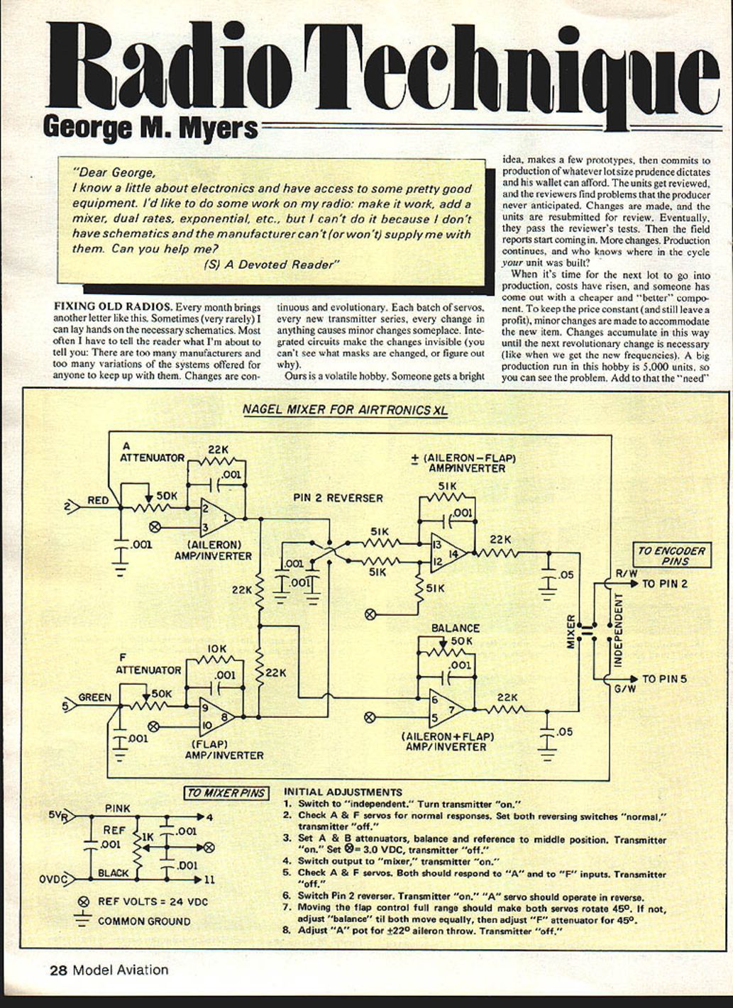
With that preamble over with, we're going to jump down inside my son's Airtronics XL transmitter, to install a mixer offered by reader Alan F. Nagel. We don't have a schematic for the XL, but we do know that it uses the NE5044 chip. We will assume that all NE5044 chips are alike (at least from the standpoint of the function at each pin of the chip).
Had I not built the Ace RC Silver Seven transmitter, I wouldn't know anything about the NE5044. However, if I had read Chapter 4 of Fred's book, I would know enough about the NE5044 to know how to install the mixer (after tracing out the wires and printed circuits for the channels we want mixed). Here's how we went about the job.
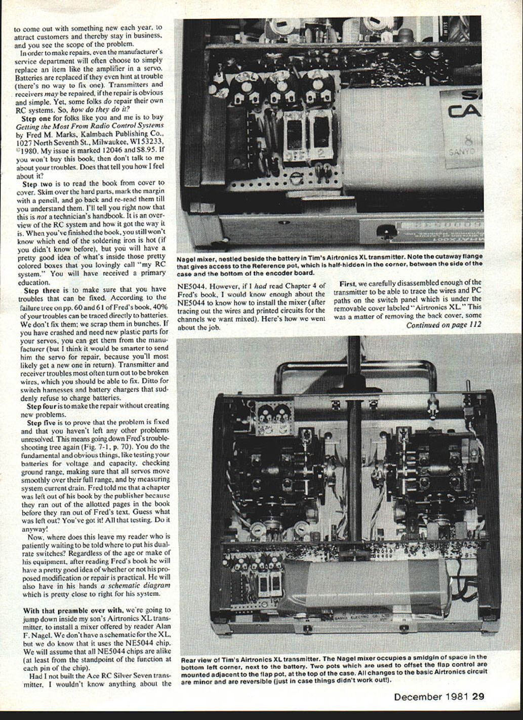
First, we carefully disassembled enough of the transmitter to be able to trace the wires and PC paths on the switch panel which is under the removable cover labeled "Airtronics XL." This was a matter of removing the back cover, some screws, the antenna, the battery, and the switchboard. Do it carefully, so as to avoid breaking anything.
Next, because Tim wanted flaperons, we traced the wires for the ailerons and flaps controls. As we traced them out, we made sketches of what we found. It soon became obvious that the XL circuits are fundamentally different from the Silver Seven circuits in Fred's book. We kept tracing and sketching until we understood the difference.
One must be very careful to avoid making assumptions that are not later proven to be true. In this case, the control voltages are distributed on Pink and Black wires. It would be easy to assume that Pink is the Japanese code for +5 VDC regulated and Black is 0 VDC, which would only be half correct! As it works out, the Pink wire connects pin 15 (+5 VDC regulated) to all the controls, but there is a 330-ohm resistor between pin 8 and the Black wire to the aileron control, which puts the Black wire at +0.7 VDC. There is also a 1,200-ohm resistor between pin 8 and the Purple wire to the flap control, which puts that point at +1.0 VDC.
Since the wiper on the control potentiometers can't move more than about 50° of its total range of about 270°, the voltages picked off by the aileron control are about +3.0 VDC ±½ VDC, measured from the battery pack negative lead, while the flap control range is about +2.7 VDC to +3.2 VDC. (These voltages were measured from a used set with freshly charged batteries, using a 20,000 ohms/volt VOM.) The resulting control pulse ranges are 1.00 ms to 2.00 ms for the ailerons and 1.10 ms to 1.90 ms for the flaps, measured with the Estes Skyaligner (Oct. '81 MA).
With this information in hand, we could decide whether or not to proceed with the proposed installation. We assembled the mixer on a piece of perfboard and ran some static tests on it. This revealed a need for an offset to the flap control voltages. When the mixed voltages are presented to the NE5044, we want Flaps Up plus Ailerons Neutral to equal +3.0 VDC. There are two ways to accomplish this purpose. One way would be to shift the flap control potentiometer shaft inside the flap control lever. This turned out to be more difficult than you'd expect, because the escutcheon plate over the flap lever is glued in place.
We opted, instead, for a pair of 5 K pots, one in series with the Pink and one with the Purple leads to the flap pot, respectively. This gave us both offset and control span adjustment. It also brought in a problem with the back of the set, which occasionally shorted out one of the pots, changing our adjustments.
INITIAL ADJUSTMENTS
- Switch independent. Turn transmitter on.
- Check A & F servos for normal responses. Set both reversing switches normal. Transmitter off.
- Set A & B attenuators (balance reference) middle position. Transmitter off.
- Switch output mixers on transmitter.
- Check A & F servos. Both should respond to F inputs. Transmitter off.
- Switch Pin 2 reverser. Transmitter servo should operate reverse.
- Moving flap control full range should make both servos rotate 45°. Adjust balance till both move equally. Adjust F attenuator for 45° aileron throw. Transmitter off.
The flaps setting was drastically wrong. Fortunately, we discovered the problem on the ground. There's no substitute for a good test program!
I don't want to drag this out like a construction article. In the end, the mixer story comes down to building the mixer (we used the wire-wrap technique described in the earlier column on the dual mixer for the Ace RC Silver Seven) and installing it between the encoder board and the Red and Green wires which are found on pins 2 and 5 of the NE5044, respectively. You can do likewise, if you feel the need—providing you read Fred's book, study the problem carefully, and test, test, test as you go.
You will void the Airtronics guarantee, and probably will have to remove the mixer and put things back the way they were, should you find the need to return the set for service. But, since the premise going into the column was that you had an old set that you couldn't get fixed, and you wanted to fix it yourself, that isn't much of a problem, is it?
Just to keep things legal, bear in mind that a 2nd-class commercial operator's license is required to do any kind of work on the RF board (or module, as the case may be). The reason for this restriction is that you can cause off-frequency operation without knowing it. Your set will seem to be working fine, but you can cause interference to pocket-pagers all over the county, or wipe out TV pictures, which you have no right to do. So, remember that George said: "Keep your cotton-picking hands out of the RF section!" — Okay?
Keep the letters flowing.
George M. Myers 70 Froehlich Farm Rd. Hicksville, NY 11801.
Transcribed from original scans by AI. Minor OCR errors may remain.

