
Radio Technique
George M. Myers
"Dear George, I'd love to buy one of those new . . . radios. They're so beautiful, and have a lot of nice features that I'd like to play with. But I'm afraid that they'll be obsolete as soon as the new narrow-band frequencies are approved. What shall I do? (S) Bewitched, Bothered & Bewildered"
Dear B, B & B, Buy now and fly later. Stop worrying. (S) George
(I've been receiving so many letters of this type lately that I can only afford time for short answers.)
THOSE NEW RADIOS
The whole question of what to do when the narrow-band frequencies come has been receiving a lot of attention. I don't think I'll be violating any confidences when I tell you that the AMA and the manufacturers have been testing the current crop of radios to see what can be done with them. Preliminary test results say that existing designs will work on the interstitial frequencies if we keep flyers at the same field separated by 40 kHz.
Another fact that has surfaced is that some of the newest radios already are sufficiently narrow-banded to work together on the 20 kHz raster originally proposed.
In an attempt to prolong the use of existing equipment as long as possible, the AMA has drafted a Phase-In Plan (discussed in the April column) which calls for the release of only those channels which will work together, taking into account wide-band receivers, image problems, intermodulation problems, drift, permitted crystal inaccuracies, etc. This plan is known to the manufacturers, and if everyone cooperates in their own best interests you won't be able to buy radios that can't get along together.
It's no secret that you can get more performance per dollar from the current crop of designs than ever before. In spite of that, sales are below expectations.
Part of the problem of low sales volume is the fault of our government. My viewpoint: Paul Volcker, head of the Federal Reserve System (independent from elected officials), has said "The American standard of living must go down" to the Senate Banking Committee. The mechanism for making this happen is usury—exorbitant interest rates. As long as the Federal Reserve keeps interest rates at usurious levels, real money is bled out of the system for no productive purpose. In this context, usury is a crime against everyone. The Bible tells us this crime has been around a long time. If we don't put a stop to it in the Federal Reserve System, the predictable result is collapse of the dollar, followed by the disappearance of businesses which make those wonderful radios. The price of R/C gear can only go up, so I repeat: Buy now.
Having said my piece, let's take a look at one of the wonderful new radios.
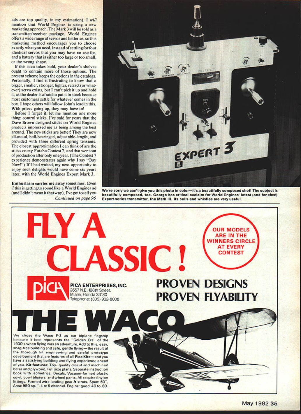
World Engines Expert Mark 3
Observers may have noticed World Engines skipped from Expert Mark 2 to Marks 4 and 5 in production. What happened to Mark 3? The Mark 3 has been clothed in a black-and-silver case and fitted with what Bill Winter refers to as "All the Bells & Whistles."
The basic design is a seven-channel system based on the 5044 chip (see Radio Technique, MA June '81 issue for description). You are offered a nice blend of control options. Let's summarize them:
- The three flight controls have linear-going-to-exponential shaping via a potentiometer on each channel that varies the curve. I heartily approve of implementing the control this way.
- Dual-rate is offered on aileron and elevator.
- Travel-reversing is offered on five channels.
- Linear electrical trim is offered on the first four channels. The trim is independent of the exponential function.
- End-point adjustment is offered on five channels. With this control you can make a servo travel more in one direction from neutral than in the other—useful on elevator, for instance, to provide the same control effect whether flying upright or inverted.
- Throttle trim affects only the low end of the range; thus the trim becomes an idle/cutoff control, which I think it always should have been.
- All the control modifiers are hidden under the back cover, where you have to work a little to get at them. I strongly endorse this approach (see my version of the Ace Silver Seven, RT MA Aug '80).
- The RF section is built on a small, independent board. This makes channel-changing simple and hedges on the type of modulation used. Shifting from AM to FM, PCM (or whatever) should be a simple matter of changing the RF board.
There are many other features in the World Engines Expert Mark 3; I'll leave it to John Maloney to tell you about them. World Engines ads are top quality, in my estimation.
World Engines is using a new marketing approach. The Mark 3 will be sold as a transmitter/receiver package. World Engines offers a wide range of servos and batteries, so this marketing method encourages you to choose exactly what you need instead of settling for four identical servos and a battery that may be too large, too small, or the wrong shape. If this idea takes hold, your dealer's shelves ought to contain more options instead of keeping them only in the catalogs.
Before I forget: control sticks. The Dave Brown–designed sticks on World Engines products have always impressed me. The new sticks are better—now all-metal, ball-bearing, adjustable-length, and provided with three different spring tensions. The closest approximation I can think of are the sticks on my Futaba Contest 7, which went out of production after only one year. (The Contest 7 experience again reinforces why I say "Buy now!" If I had waited, my next opportunity to enjoy such delights would have come six years later, with the World Engines Expert Mark 3.)
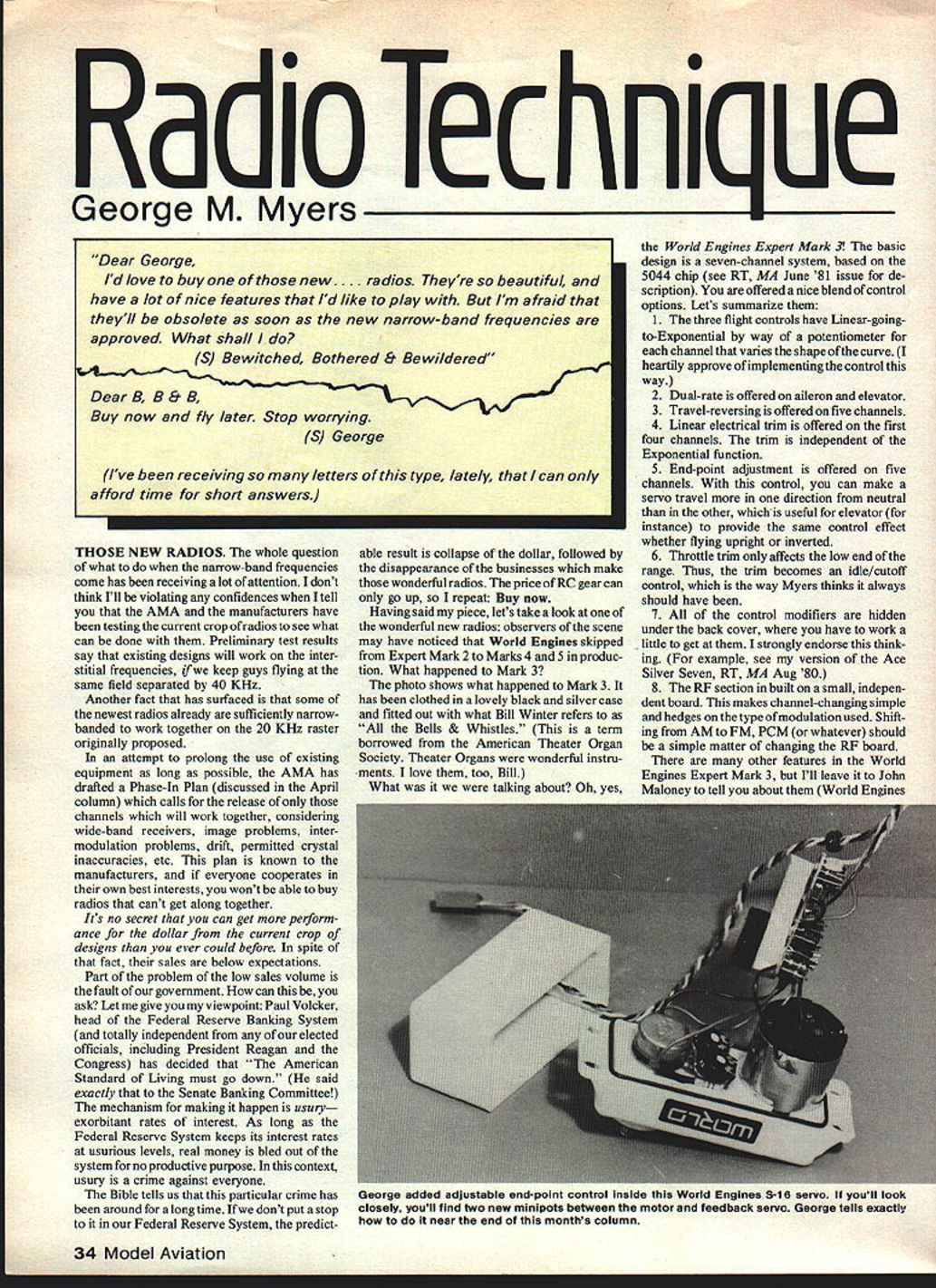
S-16 Servo — Adjustable End-Point Control
I want to mention an older World Engines product, the S-16 servo. If I were teaching a class in servo maintenance, the S-16 would be my training aid. It has big parts, lots of room inside the case, and is rugged enough to stand up to abuse.
I've been using the S-16 as a sail control unit on my 36/600 and M-class boats, and it works great. The sails really jolt the gears when they jibe, and the sustained load that they put on the servo when sailing on a reach or run in a strong wind is awesome. I haven't seen any signs of deterioration after a year of hard sailing. The S-16 gear teeth are massive relative to the usual airplane servo, so they absorb shocks and keep going. The ball bearing on the output shaft is the same type used on the crankshaft of an OS .25, so you can see it is overdesigned. The case is sealed with O-rings, so you might think the servo was designed with this use in mind (but it wasn't).
The only quibble is that a one-millisecond pulse-width change produces only a 90° servo arm throw. Sailors prefer a throw of 135° to 180°. The gears allow 175° between the stops, so a simple electrical change can provide the extra travel. Because there is plenty of room inside the case, here's how you can have adjustable end-point control inside the servo.
Parts required
- Two 1/4-watt, 1 kΩ subminiature potentiometers (Radio Shack 271-333 or equivalent)
- One 4.7 kΩ resistor (4700 ohm; color bands: yellow, purple, red, silver)
- Small soldering iron and thin solder
- Wire cutters and pliers
- (Optional) small piece of foam — see instructions
Procedure
- Open the servo case. Locate the potentiometer (the feedback pot) inside the servo and the three wires connected to it (typically black, green, and red).
- Unsolder the black wire from the servo's potentiometer and solder it to the right-hand lug of one of the 1 kΩ pots (viewing the 1 k pot with its two outer lugs toward you).
- Unsolder the green wire from the servo pot and solder it to the left-hand lug of the other 1 kΩ pot.
- Clip the points off the four outer lugs of the two 1 kΩ pots if necessary to make them flush, leaving the lugs that come from beneath the pots intact.
- Put the leads from the 4.7 kΩ resistor—one lead in each of the outer lugs of the servo's original potentiometer (i.e., into the holes where the black and green wires originally were).
- Put the center (wiper) terminal of the pot that now has the green lead into the left-hand lug position of the servo potentiometer (so the wiper feeds back into the servo pot as required).
- Solder all joints and trim excess wire and solder.
- Reassemble the internals neatly. Discard the 3/4-inch square of black foam that may get in the way. The remaining components should fit into the case if arranged carefully.
- Plug the servo into your radio, set the two 1 kΩ pots to the middle of their ranges, and test the servo throw. Small adjustments of the two pots should give you the desired end-point travel (up to about 175° if the gear stops allow it).
Simple, no?
Keep the letters flowing.
George M. Myers 70 Froehlich Farm Rd. Hicksville, NY 11801
Transcribed from original scans by AI. Minor OCR errors may remain.

