
Radio Technique
George M. Myers
New Frequencies, Old Frequencies, and Scanners
Frequency Monitoring means listening to what is going on in the RC channel you propose to use before you turn on the transmitter. Frequency Control means making some kind of provision to assure that no one else tries to use the same channel while you are using it.
I expect new frequencies to be available for the 1983 season. This raises two problem areas:
- Continued use of the seven existing even-numbered 72–76 MHz frequencies. With increasing interference, during the five-year "grandfather" period a scanner may become virtually a necessity to make flying possible.
- Beginning use of many odd-numbered 72–76 MHz frequencies, some of which may have existing interference (the justification for providing many frequencies). A scanner will tell you which channels to avoid in your area and should guide purchasing decisions.
Types of Interference
- Other modelers on the same channel. Frequency-control methods (the "clothespin" idea) work when everyone follows them, but they break down when someone ignores the rules or forgets to remove/replace clips or leaves a transmitter on. Proper use of a scanner can eliminate some of these problems.
- Commercial users. These signals are often intermittent and randomly spaced in time; a short check just before turning on your transmitter is not sufficient to detect them reliably.
- Intermodulation. Occurs when two transmitter signals enter a receiver's RF section, beat against one another, and produce a signal on a third channel (which may be the channel you are trying to use).
- Image problems. Rare; occur when a receiver is midway (frequency-wise) between two transmitters separated by exactly double the receiver IF. When an image exists, the scanner will show the two strong inputs and the sound will not match the channel you think you are listening to.
References: Electronic Bird-Dog column (Radio Technique, January 1982) and contributions by Bill Herschberger in AMA News (January 1981).
Airtronics Scanner Evaluation
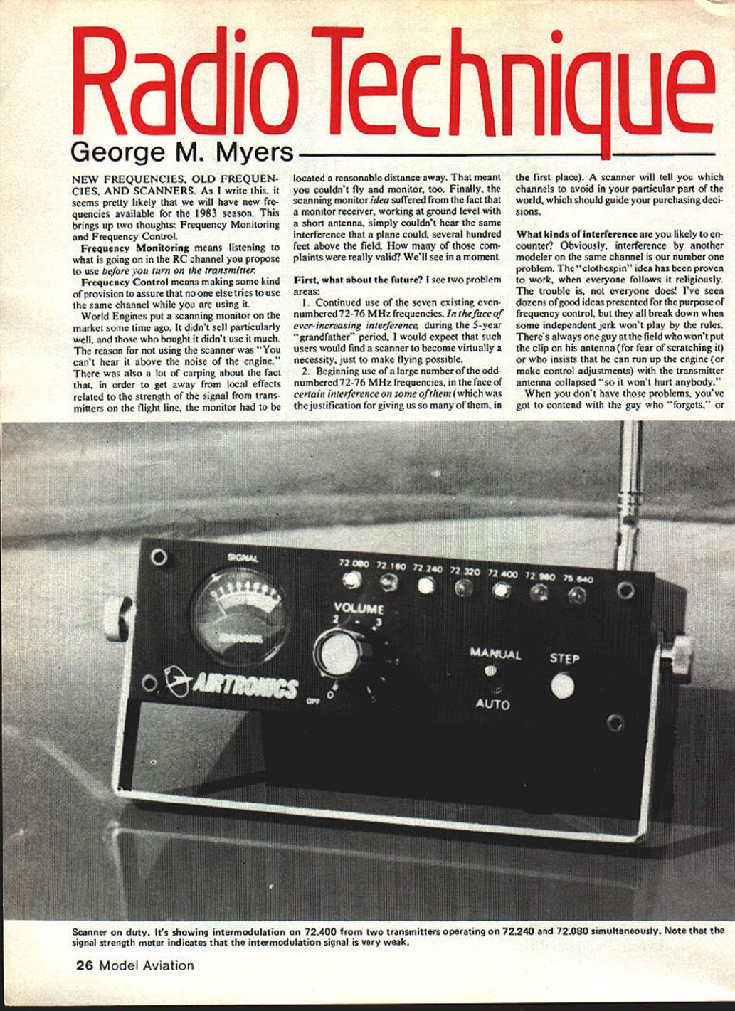
Airtronics provided a scanner for evaluation. The unit indicates the presence of a signal in four ways:
- Loudspeaker that makes a BRRR sound when receiving an AM RC signal.
- Row of LEDs that latch ON when receiving a sufficiently strong signal.
- Signal-strength meter.
- Movable whip antenna (can be positioned anywhere in a hemisphere).
Example: Stopping the scan on channel 72.40 produced the BRRR and lit the LED, but the meter read zero. This indicates intermodulation present on 72.40 with very low relative signal strength; actual interference should be minimal unless the affected model passes very close to the intermodulating transmitters. Signal strength perceived by a receiver varies inversely with distance; proximity can make an intermodulation result stronger than the intended control signal.
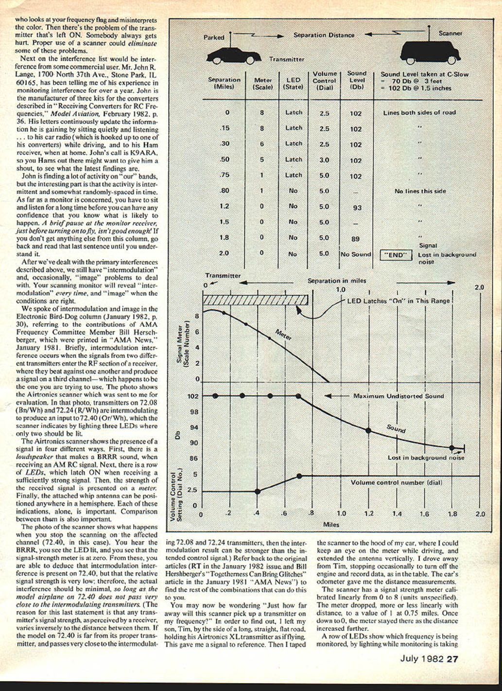
Field-distance test
To measure pickup range I used my son Tim with an Airtronics XL transmitter standing by a long, straight, flat road. I taped the scanner to the hood of my car with the antenna vertical and drove away, recording odometer distances.
- The meter is linear from 0 to 8. The meter dropped roughly linearly with distance, reaching a value of 1 at 0.75 miles and 0 at greater distances.
- LED latching ceased at about 0.75 miles.
- Loudspeaker output was measured with a Radio Shack sound level meter (microphone placed directly over speaker). Distortion corresponded to about 102 dB at a volume dial setting of 2.5 (dial marked 0–5).
- 102 dB held out to 0.30 miles at dial 2.5.
- From 0.30 to 0.75 miles, it was necessary to increase the dial setting linearly with distance to maintain 102 dB.
- At 0.75 miles the volume control was at 3.5; beyond that distance the sound level dropped following inverse-square behavior until the signal was lost in background noise at about 1.9 miles.
Conclusions from the test:
- The scanner will pick up transmitters well beyond visual range and far enough to detect other ground-level transmitters at flying sites separated by up to 1.5 miles.
- Don’t overload the scanner by holding a transmitter very close to it — the unit is sensitive and will show multiple LEDs when overloaded.
How to Use a Scanner at the Field
- For monitoring while flying, place the monitor 500–1,000 feet away from the flight line. Use a CB for communications between the monitor and the pits; the monitor operator should be in a car with a CB and a portable unit in the pits can be used as the other end.
- When you detect interference:
- Stop the scan on the affected channel (AUTO/MANUAL).
- Compare the audio character, antenna direction, LEDs, and meter reading.
- Log the time and describe what you heard; over time you’ll build a useful file.
- Current monitor coverage (Airtronics unit): 72.08, 72.16, 72.24, 72.32, 72.40, 72.96 and 75.64 MHz. Additional frequencies can be monitored by crystal swapping.
- Bandwidth: The AMA draft Phase-In Plan places new frequencies 40 kHz apart, which has been demonstrated acceptable for existing receiver designs and should not be a significant problem.
Power, Portability, and Observations
- The Airtronics scanner is self-contained and portable. Power options:
- Alkaline pencil cells: ~8 hours.
- Ni-Cd: ~5 hours.
- Charger that plugs into the cigarette lighter.
- Example uses: Doug Pratt has run an Airtronics scanner in the AMA headquarters in downtown DC (using an Airtronics transmitter charger). At home in Hicksville I detected nothing, but at the road I found musical tones like pushbutton telephone signals and occasional voices; laying the whip antenna parallel to the ground produced many BRRR signals over the flying field. Suspected sources include computer data transmissions from nearby towers and varied antennas.
Image Problems, Converters, and the Bird-Dog
- Image problems: Jack Albrecht (AMA Frequency Committee) accounted for image issues in the draft Phase-In Plan; if followed, systems susceptible to image problems should not be sold. The 72.08/72.96 proximity issue will disappear after the five-year period.
- Using non-R/C scanners: Yes, you can use general scanners for R/C with the proper converter. Contact:
- John R. Lange, 1700 North 37th Ave., Stone Park, IL 60165. Call sign K9ARA. John manufactures converter kits described in "Receiving Converters — R/C Frequencies" (Model Aviation, February 1982, p. 36) and continuously updates monitoring information.
- Electronic Bird-Dog (Radio Technique, January 1982): A low-cost solution that monitors only the channel your receiver is on but does so well. It draws about 300 mA (will discharge a typical 500 mAh pack in under two hours). For continuous monitoring, add a 100-ohm resistor in series with the loudspeaker to reduce current drain to about 35 mA.
Conclusion and Contacts
A scanning monitor is a useful tool for frequency monitoring and frequency control as we move into the new 1983 season. It will not cure all problems but will identify primary sources of interference, guide frequency choices, and tell you which channels to avoid in your area.
If you want to buy the Airtronics scanner, contact: Airtronics 12160 Woodruff Ave., Downey, CA 90241 Telephone: (213) 862-6583
Keep the letters flowing.
George M. Myers 70 Froehlich Farm Rd., Hicksville, NY 11801.
Transcribed from original scans by AI. Minor OCR errors may remain.

