
Radio Technique
George M. Myers
Letter from a reader
Dear George,
Having just read your article in the January 1983 issue, I decided to write to you. In your article, you made reference to the almost-frictionless characteristics of coreless motors. Since I have just ordered a new Airtronics Championship Series radio with the coreless-motor servos, I am quite interested in them.
Just from looking at the specs on coreless-motor servos, one can see that they are powerful and fast for their physical size. But in all the ads and talk about them, no one has explained how coreless motors work, or how they are constructed compared to the conventional 3- or 5-pole motor. Would you do this for me, and for possibly some other readers who may have the same question?
(s) Don Austin, AMA 19871
---
How conventional DC motors are built and why they "cog"
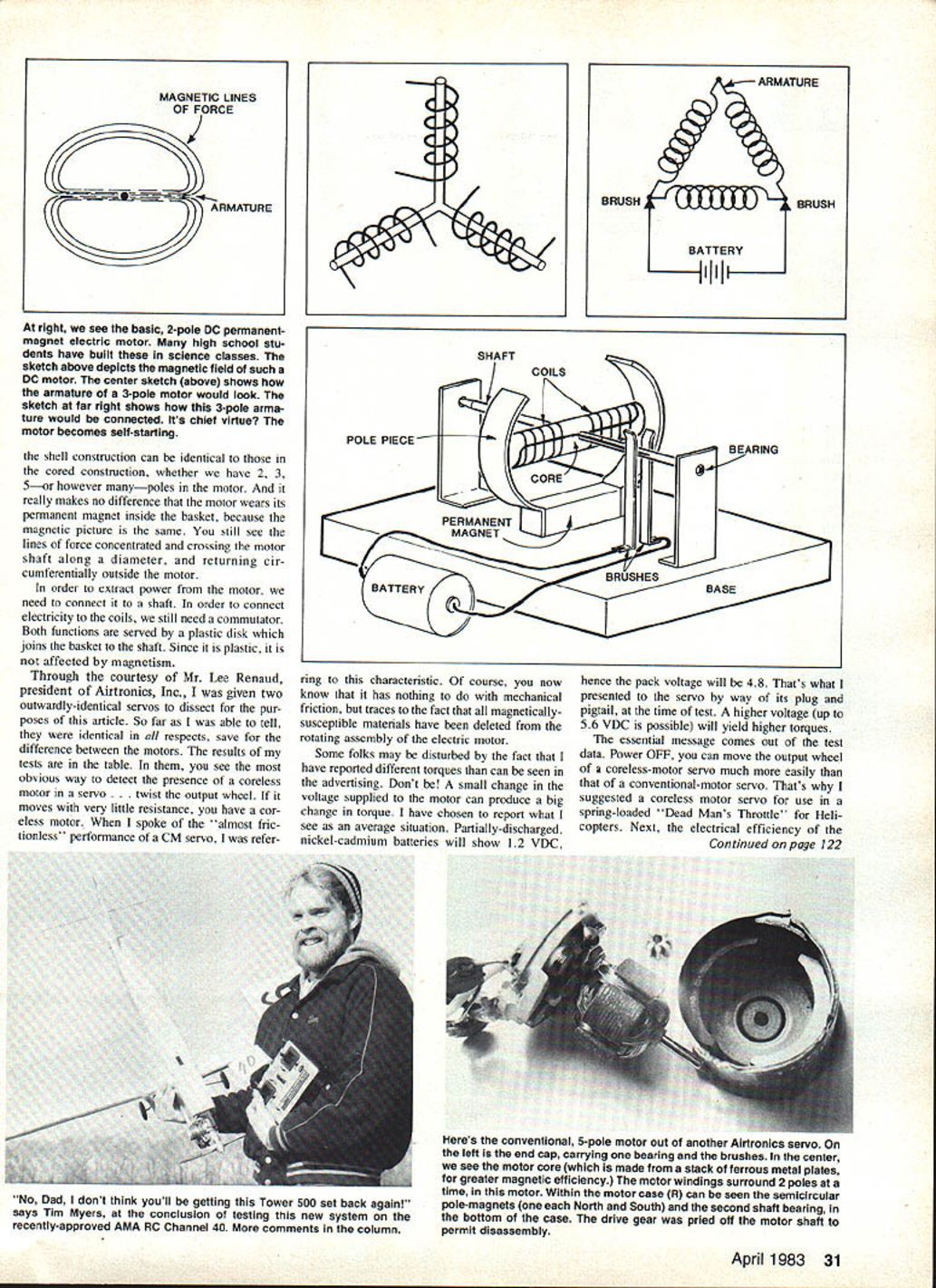
Many who have taken an elementary course in electricity will have built an electric motor in rudimentary form. Use a piece of iron stuck on a shaft in the manner of a propeller. Wind a coil of copper wire about the iron, bringing the coil ends out along the shaft on opposite sides of the shaft diameter. Fasten the wires in place with insulating material and use the assembly to make electrical contact to the coil; call it a commutator.
Next mount the shaft on supports that allow the motor to spin freely. With the iron bar, coil and commutator mounted on the shaft bearings, the iron bar alone is the core of the motor. In order to bring power to the motor, fasten a pair of wires to a battery and let the ends rest on the commutator; the wires are called brushes in DC electric motors.
Because electrical current is flowing in the coil, the iron bar becomes magnetized — you have created an electromagnet, the basis of the electric motor. If you rotate the motor 180° on its shaft, the polarity of the electromagnet reverses because the commutator has reversed the electrical connections to the coil.
In this too-basic form the motor must be spun to get started. To get around this, split the core into a Y shape and wind three coils, each surrounding a leg of the Y and connected to a pair of contacts on the commutator. The commutator supports three contacts so coils draw current in overlapping sequences; the important point is that no matter where the motor stops, when current is applied the resulting forces are unbalanced and the motor starts itself. Using an odd number of poles (3, 5, 7, etc.) makes the motor self-starting and allows smoother operation as pole count increases.
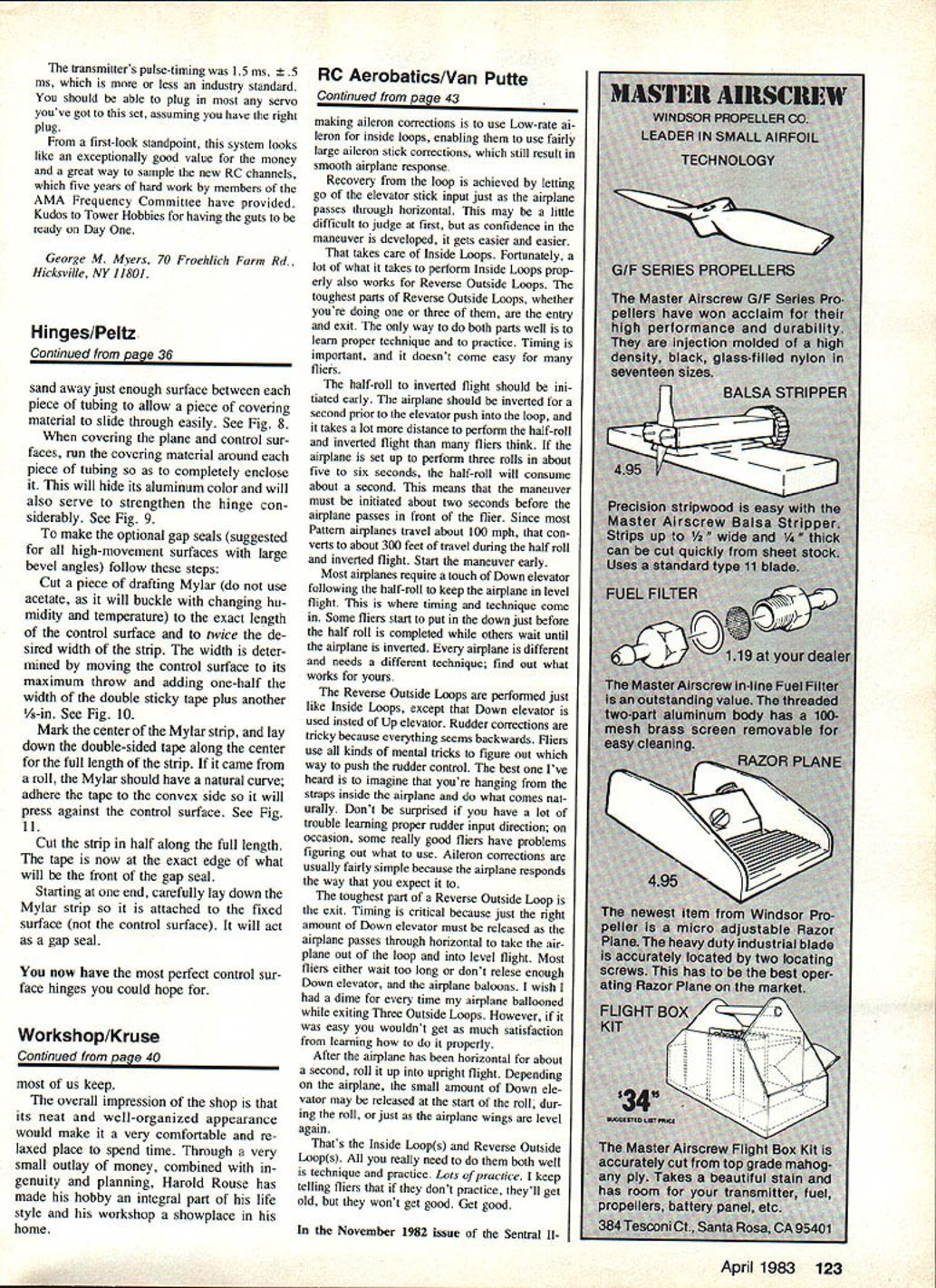
Let’s examine the core. It must be iron or another magnetically susceptible material. Its functions are to conduct the magnetic field of the permanent magnet and to concentrate the magnetic force generated by the coil. Because the core is magnetically susceptible it will try to align itself with the permanent magnetic field between the pole pieces. You must do real work to move it out of its preferred position. For example, if the core is a five-pointed star, the motor will have 10 resting positions, and when you rotate the motor with power OFF you will feel the motor "cogging" through these positions. This cogging is important to the differences that follow.
Jumping ahead a bit, it should be obvious that if you could get rid of the core, the motor would not have preferred resting positions and would spin rather freely with power OFF.
Coreless motors — construction and why they coast
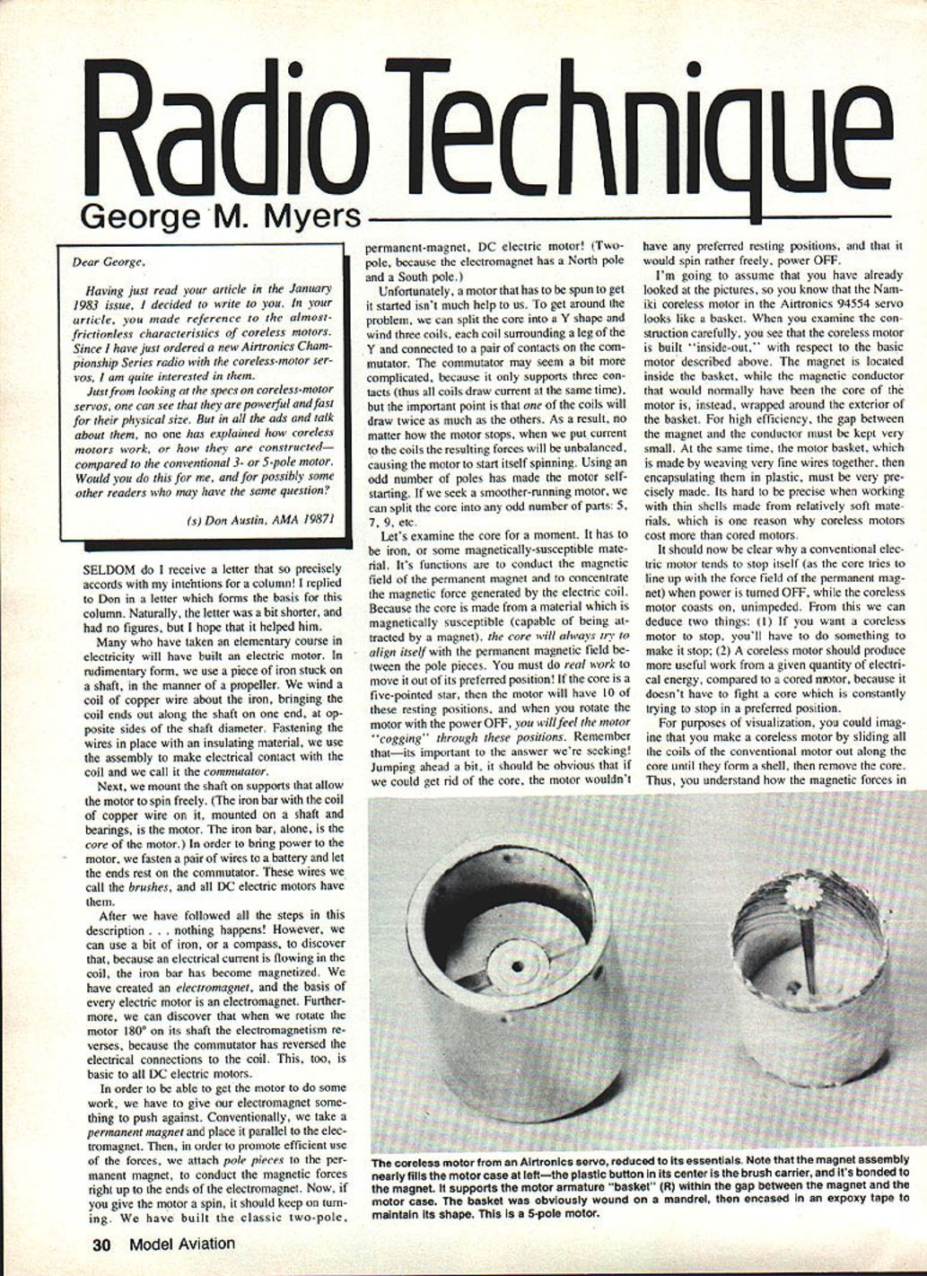
You can imagine making a coreless motor by sliding all the coils of a conventional motor out along the core until they form a shell, then removing the core. The Namiki coreless motor used in the Airtronics 94554 servo looks like a basket: the motor is built "inside-out" compared to the conventional motor. The permanent magnet is located inside the basket, while the magnetic conductor that would normally have been the core is wrapped around the exterior of the basket.
For high efficiency the gap between the magnet and the conductor must be kept very small. The motor basket is made by weaving very fine wires together and encapsulating them in plastic, and it must be very precisely made. That precision (and the difficulty of working with thin shells of relatively soft materials) is one reason coreless motors cost more than cored motors.
Because all magnetically susceptible materials have been deleted from the rotating assembly, a coreless motor does not have the magnetic "preferred positions" that make conventional motors cog when power is off. Thus a coreless motor coasts on, unimpeded, when unpowered.
From this we can deduce:
- If you want a coreless motor to stop, you must actively provide something to stop it (braking, spring load, electronic braking, etc.).
- A coreless motor should produce more useful work from a given quantity of electrical energy compared to a cored motor, because it doesn't have to fight a core that is constantly trying to return to its preferred position.
For visualization, the magnetic field picture is the same in shell (coreless) and cored constructions: lines of force are concentrated and cross the motor shaft along a diameter and return circumferentially outside the motor. The fact that the permanent magnet is inside the basket does not change the magnetic action.
To extract power you still need a shaft and a commutator. Both are served by a plastic disk which joins the basket to the shaft; being plastic, it is not affected by magnetism.
Practical notes and performance
- The most obvious way to detect a coreless motor in a servo is to twist the output wheel. If it moves with very little resistance when power is off, you have a coreless motor — the "almost frictionless" feel refers to this magnetic behavior, not mechanical friction.
- Electrical efficiency (inch-ounces per Watt for equal transit times) of a coreless-motor servo is higher, so coreless servos are attractive for duration flying.
- Because the basket of a coreless motor is so much lighter than the armature of a conventional motor, it may resist shock and vibration damage better; however, actual durability depends on design and manufacturing.
Small changes in supply voltage produce big changes in torque. The author reported test values using partially discharged Ni-Cd cells (about 1.2 V each, pack voltage 4.8 V). Higher supply voltage (up to about 5.6 V) will yield higher torques.
Test comparison: Airtronics servos
- Servos compared: Airtronics 94551 (Conventional motor) and 94554 (Coreless motor)
- Torque to turn output wheel (power OFF)
- 94551: 26 ± 2 inch-ounces
- 94554: 4 ± 0.6 inch-ounces
- Idle current (no control pulse)
- 94551: 7 mA
- 94554: 7 mA
- 90° reversed-cycling transit time
- 94551: 0.5 seconds
- 94554: 0.5 seconds
- Free-running current
- 94551: 120 mA
- 94554: 40 mA
- Stall current
- 94551: 600 mA
- 94554: 800 mA
- Volts at stall
- 94551: 4.8 VDC
- 94554: 4.8 VDC
- Stall torque
- 94551: 35 inch-ounces
- 94554: 60 inch-ounces
- Motor type
- 94551: Conventional
- 94554: Coreless
Essential message from the test data:
- Power OFF, you can move the output wheel of a coreless-motor servo much more easily than that of a conventional-motor servo.
- Coreless-motor servos offer higher electrical efficiency (more inch-ounces per Watt at equal transit times), making them desirable for duration flying and applications where low off-power cogging is important (for example, a spring-loaded "Dead Man's Throttle" for helicopters).
---
A NEW RADIO, NEW RC CHANNELS
First look at the Tower 500. If you're like me, you aren't inclined to take the new crop of low-priced radios very seriously. A case in point is the Tower "Gold System 500," which offers a plug-in crystal right on the front panel, dual rates on aileron and elevator, servo-reversing on aileron, elevator, rudder and throttle, electric trims, a trainer button, an output meter, all Ni-Cd power, charger, receiver, and four servos for less than $150. (I paid more than that for just the receiver in my 1971 Pro-Line!)
Tower Hobbies sent the radio with crystals on both ends of the 72 MHz band (and one in the middle of channels 12, 40 and 56). According to Tower's Bill Baxter, the sets come in without crystals and Tower supplies whatever you request from a stock of .001% crystals; then they check for a 100-ft. ground range (transmitter antenna collapsed, receiver antenna dangling out of the box) inside their warehouse.
Testing the claim, the author found that with adjacent-channel transmitters set up similarly, the distance ratio before servos began to jitter was 20:1, which equates to very good performance. The set is narrow enough for typical use.
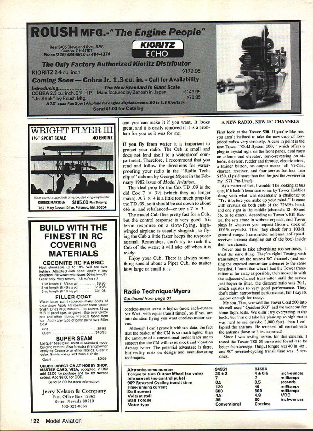
Flight tests: The author's son Tim flew a "Quickie 500" with the Tower Gold 500 transmitter. At high altitude (about 2,000 ft, hard to see) the transmitter with collapsed antenna retained full control down to 3 inches of exposed antenna.
Tower servo TSS-50:
- Output torque: 40 in.-oz.
- 90° reversed-cycling transit time: 0.5 seconds
---
Transcribed from original scans by AI. Minor OCR errors may remain.

