
Radio Technique
George M. Myers
INTERFERENCE
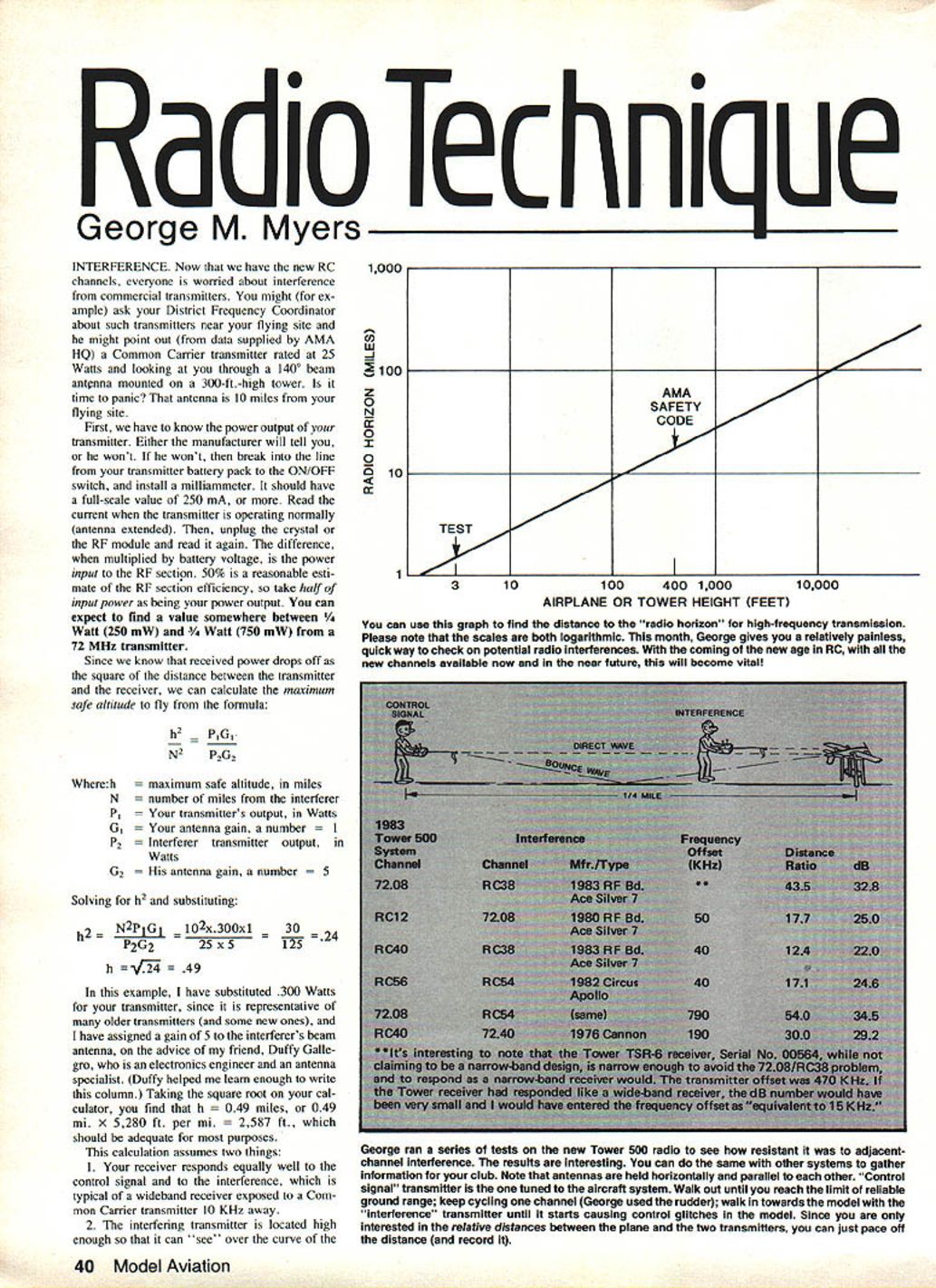
Now that we have the new RC channels, everyone is worried about interference from commercial transmitters. You might (for example) ask your District Frequency Coordinator about such transmitters near your flying site and he might point out (from data supplied by AMA HQ) a Common Carrier transmitter rated at 25 Watts and looking at you through a 140° beam antenna mounted on a 300-ft.-high tower. Is it time to panic? That antenna is 10 miles from your flying site.
First, we have to know the power output of your transmitter. Either the manufacturer will tell you, or he won't. If he won't, then break into the line from your transmitter battery pack to the ON/OFF switch, and install a milliammeter. It should have a full-scale value of 250 mA, or more. Read the current when the transmitter is operating normally (antenna extended). Then, unplug the crystal or the RF module and read it again. The difference, when multiplied by battery voltage, is the power input to the RF section. Fifty percent is a reasonable estimate of the RF section efficiency, so take half of the input power as being your power output. You can expect to find a value somewhere between 1/4 Watt (250 mW) and 3/4 Watt (750 mW) from a 72 MHz transmitter.
Since we know that received power drops off as the square of the distance between the transmitter and the receiver, we can calculate the maximum safe altitude to fly from the formula:
h^2 / N^2 = P1 G1 / P2 G2
Where:
- h = maximum safe altitude, in miles
- N = number of miles from the interferer
- P1 = Your transmitter's output, in Watts
- G1 = Your antenna gain (use 1)
- P2 = Interferer transmitter output, in Watts
- G2 = His antenna gain (use 5)
Solving for h^2 and substituting:
h^2 = N^2 P1 G1 / P2 G2 = 10^2 × 0.300 × 1 / (25 × 5) = 30 / 125 = 0.24
h = √0.24 = 0.49
In this example, I have substituted 0.300 Watts for your transmitter, since it is representative of many older transmitters (and some new ones), and I have assigned a gain of 5 to the interferer's beam antenna, on the advice of my friend Duffy Gallegro, who is an electronics engineer and an antenna specialist. Taking the square root on your calculator, you find that h = 0.49 miles, or 0.49 mi × 5,280 ft/mi = 2,587 ft., which should be adequate for most purposes.
This calculation assumes two things:
- Your receiver responds equally well to the control signal and to the interference, which is typical of a wideband receiver exposed to a Common Carrier transmitter 10 kHz away.
- The interfering transmitter is located high enough so that it can "see" over the curve of the earth the airplane.
George ran a series of tests on the new Tower Gold 500 radio to see how resistant it was to adjacent-channel interference. The results are interesting. You can do the same with other systems to gather information for your club. Note that antennas are held horizontally and parallel to each other. The "control signal" transmitter is the one tuned to the aircraft system. Walk out until you reach the limit of reliable ground range; keep cycling one channel (George used the rudder); walk in towards the model until the "interference" transmitter starts causing control glitches in the model. Since you are only interested in the relative distances between the plane and the two transmitters, you can just pace off the distance (and record it).
As you can see, it's a simple calculation which can be quickly made. A cheap pocket calculator is all anyone should need.
Some interferences can happen right on the field. Jack Albrecht, National Sales Manager for Kraft Systems and the Frequency Committee member who had the most to do with preparing the Phase-In plan, has pointed out that certain of the new channels are only 15 kHz from the high-side local oscillator frequency of the old channels. The combinations are 72.08/RC38, 72.16/RC42, 72.24/RC46, 72.32/RC50, 72.40/RC54, and with a converted wideband receiver on the new channel, or a non-converted wideband receiver in the old system, interference might occur when they are flying from the same flight line. If it does occur, have these pairs share the same frequency pin on your clipboard, or send one-half of each pair to fly at a nearby field, which isn't such a bad idea if you can work the channel-splitting with another club. Once split, these guys will be better off than some of the folks on the other channels.
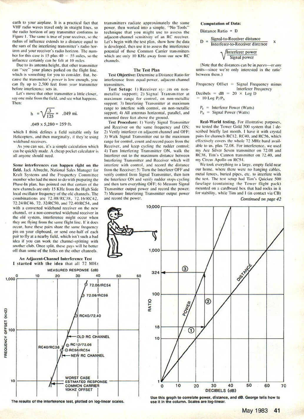
An Adjacent-Channel Interference Test
I started with the idea that all 72 MHz transmitters radiate approximately the same power, then worked into a simple, "no tools" technique that you might use to assess the adjacent-channel sensitivity of an RC receiver.
Let's begin with the test plan, show how the data is developed, then use it to assess the interference potential of those Common Carrier transmitters which are only 10 kHz away from our new RC channels.
The Test Plan
Test Objective:
- Determine a Distance Ratio for interference from equal-power, adjacent-channel transmitters.
Test Setup:
- Receiver system on non-metallic support.
- Signal Transmitter at maximum range for control, on non-metallic support.
- Interfering Transmitter at maximum range to interfere with control, on non-metallic support.
- All antennas horizontal, parallel, and mounted three feet above the ground.
Test Procedure:
- Verify Signal Transmitter and Receiver on the same frequency and ON.
- Verify Interferer on adjacent channel and OFF.
- Walk Signal Transmitter out to the maximum range for control, count and record paces from the Receiver, and keep cycling the rudder control.
- Turn Interfering Transmitter ON, walk the Interferer out to the maximum distance between Interfering Transmitter and Receiver which will interfere with control, and record the distance from the Receiver.
- Turn the Interferer OFF and verify control from Signal Transmitter, then turn the Interferer ON and verify rudder stops cycling, and then turn everything OFF.
- Measure Signal Transmitter output power and record the power.
- Measure Interfering Transmitter output power and record the power.
Computation of Data
Distance Ratio = D
D = (Signal-to-Receiver distance) / (Interferer-to-Receiver distance) × sqrt(Interferer power / Signal power)
(Note that the distances can be in paces—or any units—since we're only interested in the ratio between them.)
Frequency Offset = Signal Frequency − Interferer Frequency
Decibels:
- dB = 20 × log10(D) = 10 × log10(Pi / Ps)
Where:
- Pi = Interferer Power (Watts)
- Ps = Signal Power (Watts)
Real-World Testing
For illustrative purposes, we tested the Tower Gold 500 system that I described briefly last month. I have it with crystal pairs for channels RC12, RC40, and RC56, which effectively covers the whole 72 MHz band available to us, plus 72.08. For interference, we used my Ace Silver Seven transmitter on 72.08 and RC38, Tim's Cannon transmitter on 72.40, and Circus Apollo on RC54.
We took everything to a large, empty field near our home, where there were no hanging cables, metal fences, buried pipes, etc., to interfere with the test. The test setup had Tim's Quickee 500 fuselage (containing the Tower flight pack) mounted on a cardboard box that had rocks in it for stability, while Tim and I (in contact via CB) held the transmitters and performed the test. All RC transmitter antennas were held horizontally and parallel. Tim's friend Marilyn Dikeman monitored the airplane and signalled the happenings to us.
We performed the tests to obtain a passband estimate. I must emphasize that this is not the response curve you will find in the manufacturers' literature. Their curves will be taken in sterile, laboratory conditions — receiver only. My curve is taken from the real world. All components are in their usual places and all antennas are close to the ground, which makes a great big difference. My signal sources are real antennas, which also is important.
Holding the antenna horizontally puts the system into horizontal polarization. The radio waves go to the receiver antenna two ways, both perpendicular to the antenna, therefore at equal strength. One wave goes direct through the air, the other bounces off the ground, which inverts the wave. Thus, the two waves arrive at the receiver antenna 180° out of phase, affording almost total cancellation. The cancellation isn't total because there is a tiny difference in path length, and a tiny reduction of signal strength in the reflected wave, since the reflection isn't perfect. The practical result of all this is that the ground range (antenna extended) is about 1/4 mile, while the air range (overhead) is several miles. The greater air range is a result of the fact that RF energy leaves your antenna in all directions, but has least strength parallel to the antenna. Any reflected wave to the plane in the sky is likely to have started from the antenna at reduced power, due to the angles involved, so sky range can be (and is) much greater than the test situation I have set up here.
After plotting the test data on log-linear paper and fitting a straight line to it, we can estimate that the response of this receiver may be −17 dB at 10 kHz off the RC channel frequency, which is where we find those Common Carrier transmitters everyone is so worried about. Use conversion between dB and Distance/Power Ratios to find the corresponding Distance Ratio = 7 and Power Ratio = 50.
The Distance Ratio tells us that the reduced sensitivity 10 kHz away from the RC channel center means that the Common Carrier transmitter affects our receiver as if the transmitter were seven times farther away than it really is. For example, using N = 1 mile:
Without correction: h^2 = N^2 P1 G1 / P2 G2 = 1^2 × 0.300 × 1 / (25 × 5) = 0.0024 h = √0.0024 = 0.049 mi = 0.049 × 5,280 = 259 ft.
Applying Distance Ratio = 7 (i.e., interferer appears 7× farther): h^2 = (7 × 1)^2 × 0.300 × 1 / (25 × 5) = 0.1176 h = √0.1176 = 0.343 mi = 0.343 × 5,280 = 1,811 ft.
So, multiplying the original 259 ft by 7 gives about 1,813 ft — much more reasonable.
Alternatively, the Power Ratio tells us that the reduced sensitivity 10 kHz away from the RC channel center means that a Common Carrier transmitter must be 50 times more powerful than our transmitter to have the same effect. Using Power Ratio = 50 (effective increase in numerator):
h^2 = N^2 × P1 × PowerRatio / (P2 × G2) = 1^2 × 0.300 × 50 / (25 × 5) = 0.12 h = √0.12 = 0.3464 mi = 0.3464 × 5,280 = 1,829 ft.
Either method gives roughly the same result. Important: you can apply one correction or the other, but not both. The closer you fly to the ground, the more accurate this assessment will be.
Important Point
You should realize that all of the above testing would be unnecessary if the manufacturers would supply you with three pieces of information:
- Their transmitter output power.
- Their receiver's response 10 kHz off the channel center.
- Their receiver's response 40 kHz off the channel center.
It may be that they will give you that information in terms of "so many dB down" — or "-dB." In either case, read the dB and convert to Distance or Power Ratios. This is a plea to all manufacturers for publication of that information.
They won't provide these figures unless you demand them, and you won't get them until you convince them that you will be able to use them in a fair and intelligent manner. I think you can do it. Go get 'em!
George M. Myers 70 Froehlich Farm Rd. Hicksville, NY 11801.
Transcribed from original scans by AI. Minor OCR errors may remain.

