
Radio Technique
George M. Myers
BASED ON THE dozens of letters, phone calls and visits I have received since publication of the January 1976 issue, there must be a few hundred members who have built Corley's Critical Voltage Indicator (CVI) and are having problems. This column is directed to them.
Let's begin by saying that the CVI works. Every time that I've had the opportunity to examine one that wouldn't, it was built wrong. The most common mistakes were reversed diodes, improperly connected UJTs and 82K (Grey, Red, Orange) where it belongs. So, if you still have some components to work with, let's go at this thing systematically.
Begin with four new flashlight batteries. Connect them nose-to-tail in a series string, with a short wire from each intersection to provide a power supply tapped at 0, +3, +4.5 and +6 volts (Fig. 1). Take the LED and connect its + lead to +3 and its - lead to +4.5. If the LED does not light, exchange the connections. Wrap a piece of tape around the lead connected to +3 when the LED is glowing and mark it "to B1" (Fig. 2).
Now take the diode (any switching diode, such as the 1N914, can be substituted for the 1N4009) and insert it between the LED and the +3 lead from the power supply. If the LED stops glowing, reverse the diode connections. Mark the diode lead connected to the LED when it is glowing "to E" (Fig. 3). Set the diode aside and take up the UJT. Since the article was written, Radio Shack has discontinued the 276-111, so you may have to use a Motorola HEP No. 310 or S9002, which can be obtained from electronic supply houses like Lafayette Radio Electronics Corp., 111 Jericho Turnpike, Syosset, NY 11791.
Spread the UJT leads so that you can connect one lead to +3 and another to the LED. If the LED lights, mark the lead to +3 "E" (Fig. 4). If the LED doesn't light, keep switching the UJT leads around until it does, mark the lead.
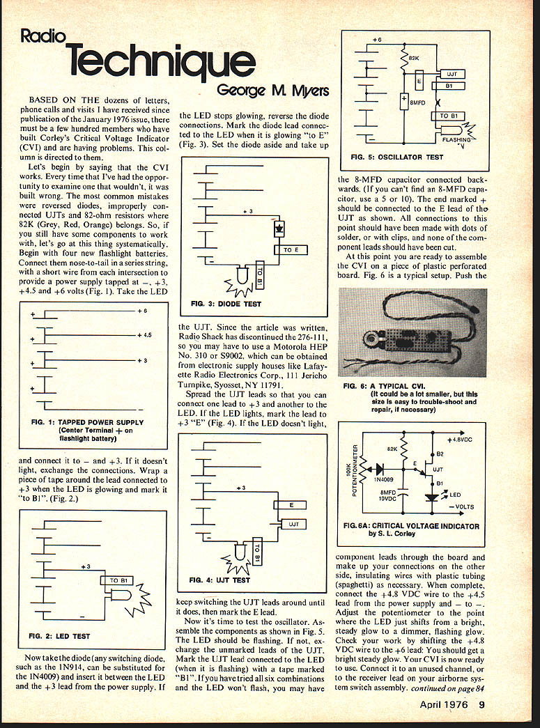
Now it's time to test the oscillator. Assemble the components as shown in Fig. 5. The LED should be flashing. If not, exchange the unmarked leads of the UJT. Mark the UJT lead connected to the LED (when it is flashing) with a tape marked "B1". If you have tried all six combinations and the LED won't flash, you may have the 8‑MFD capacitor connected backwards. (If you can't find an 8‑MFD capacitor, use a 5 or 10.) The end marked + should be connected to the E lead of the UJT as shown. All connections to the point should have been made with dots of solder, or with clips, and none of the component leads should have been cut.
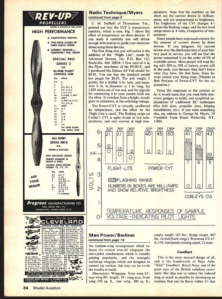
At this point you are ready to assemble the CVI on a piece of plastic perforated board. Fig. 6 is a typical setup. Push the component leads through the board and make up the connections on the other side, insulating wires with plastic tubing (spaghetti) as necessary. When complete, connect the +4.8 VDC wire to the +4.5 lead from the power supply and - to -. Adjust the potentiometer to the point where the LED just shifts from a bright, steady glow to a dimmer, flashing glow. Check your work by shifting the +4.8 VDC wire to the +6 lead; you should get a bright steady glow. Your CVI is now ready to use. Connect it to an unused channel, or to the receiver lead on your airborne system switch assembly. C. M. Duffield of Thomaston, Tex., pointed out that the UJT is temperature sensitive, which is true. Fig. 7 shows the effect of temperature on three devices. If you study it carefully you will obtain enough information to guide your decisions about using these devices.
The first thing that you will notice is the addition of the "Flight Lite", made by Advanced Devices, Inc., P.O. Box 152, Rockville, Md. 20850. I first read of it in the Flyer, newsletter of the PGRC, and purchased the Deluxe 4.8 Volt model for $9.95. You can buy the standard model (no plugs) for $6.95. The unit weighs 2 grams, fits a drilled 1/4 in. hole, and measures 1/4 in. in diameter x 1 in. long. An LED sticks out of one end, and the pigtails for connecting it to your system stick out the other. It switches from a bright, steady glow to extinction, at the switching voltage.
The Power-CYT is virtually unaffected by temperature, and the effect on the Flight Lite is small. The flashing range on Corley's CVI is quite broad at low temperatures, and very narrow at high temperatures.
Note that the numbers on the chart are the current drawn in milliamperes, and are proportional to brightness. The brightness of the CVI changes 4:1 across the flashing range, and the low level range starts at 4 volts, irrespective of temperature.
Some people have expressed concern for the amount of current drawn by these devices. If you integrate the current draw over the discharge time of your battery pack in service, you will see that the power consumed is on the order of 5% of available power. Most people will stop flying with 30% to 50% of battery power still in the pack, just because they don't know what they have. On that basis, these devices extend your flying time. (Thanks to Bob Petrinec of Power-CYT for the explanation.)
From the responses to the column so far it would seem that you want little electronics gadgets to build, and simplified explanations of traditional RC techniques (like bolt sizes, propeller sizes, hinging installations, etc.). If you want something else, my address is: George M. Myers, 70 Froehlich Farm Road, Hicksville, N.Y., 11801.
Transcribed from original scans by AI. Minor OCR errors may remain.

