
Radio Technique
George M. Myers
Tuning Your Receiver
Every so often I receive another pound of newsletters from AMA HQ. Based on what I read there, some folks are overreacting to possible RC interference. While it is good to be aware of what may happen, I think it is wrong to tell ourselves that it will always happen and thereby start limiting ourselves unnecessarily.
In point of fact, I have been flying on the new RC channels for the past six months and have deliberately invited every kind of potential interference that I've seen discussed. So far, using radios built in 1970, 1976, 1978, 1980 and 1982, and setting up for adjacent-channel (40 kHz) interference, second-order and third-order intermodulation and image, the main thing I've discovered is that there isn't any problem. If my test results mean anything, then I say your old radios will work fine on the new RC channels if you just use your head: keep a little distance between transmitters (20 ft. or so), stick to the AMA RC Frequency Control Plan, keep your receivers in tune, don't taxi in the pit area, do a little monitoring and testing when necessary, and you'll make out fine.
As an example, Bob Aberle, Tom Hunt, and I went out the other day to run another test. With Bob on 72.400 (O/W), Tom on RC54 (72.870) and me with the plane on RC40 (72.590) we stood in a bunch with the transmitters ON and the antennas extended. The plane showed us interference. I sent Bob out 15 ft. to one side, Tom out 15 ft. in the opposite direction, and the interference went away.
Then I fired up the engine, took off, flew around over our heads—up high, down low—and landed, all without a sign of trouble. Then we changed my system to RC56 and repeated the test. Again, no problems. That's a typical test, and its result.
By the numbers, when you subtract 72.400 from 72.870 you get a .470 mixing product in any receiver. If your .455 IF amplifier is broad enough, the .470 can get through to cause interference. On the other hand, if the IF is properly tuned it will reject the interference, and that's exactly what happened for me. Another bugaboo put to rest!
The Problem
The common interference modes and suggested responsibilities are:
Adjacent-Channel Interference
Manufacturer:
- Narrow-band receiver design
- Proper tuning
User responsibility:
- Be aware of the possibility
- Proper maintenance
- Receiver tuning, when necessary
- Monitoring of RC bands
- Flight stations separation
2nd Order Intermodulation
Manufacturer:
- Narrow-band receiver design
- Proper tuning
User responsibility:
- Be aware of the possibility
- Proper maintenance
- Receiver tuning, when necessary
- Monitoring of RC bands
- Flight stations separation
3rd Order Intermodulation
Manufacturer:
- Transmitter 2nd harmonic suppression by design
- Proper tuning
User responsibility:
- Be aware of the possibility
- Proper maintenance
- Monitoring of RC bands
- Flight stations separation
Image
Manufacturer:
- Dual-conversion or "odd-IF" receiver design
- Proper tuning
User responsibility:
- AMA RC Frequency Control Plan
- Be aware of the possibility
- Monitoring of RC bands
- Flight stations control card
Test Results (Aberle & Hunt)
From the test with Aberle & Hunt:
Sums:
- 73.045 + 72.87 = 145.915
- 73.045 + 72.59 = 145.635
- 73.045 + 72.40 = 145.445
- 72.87 + 72.59 = 145.46
- 72.87 + 72.40 = 145.27
- 72.59 + 72.40 = 144.99
Differences:
- 73.045 - 72.87 = 0.175
- 73.045 - 72.59 = 0.455
- 73.045 - 72.40 = 0.645
- 72.87 - 72.59 = 0.280
- 72.87 - 72.40 = 0.470
- 72.59 - 72.40 = 0.190
Frequencies used in the test:
- 73.045 (RC 40 local oscillator)
- 72.87 (RC 54)
- 72.59 (RC 40)
- 72.40 (O/W)
Note: The 0.455 mixing product is the only one we want (nominal IF).
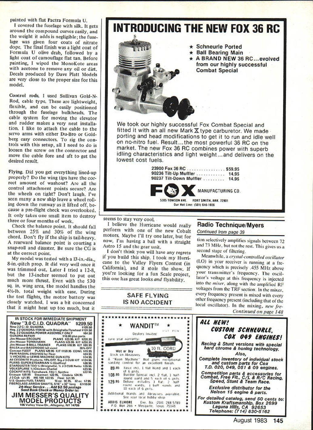
How Your Receiver Works (briefly)
Every electrical signal in the world is presented to your antenna. Your receiver must seek out and respond to your transmitter's weak signal. A TV transmitter may radiate thousands of watts while your RC transmitter only puts out about 1/2 watt, so the job of the receiver is demanding.
- Antenna: Usually cut to a specific length (about one meter) and performs the first bit of filtering, responding best to VHF signals.
- TRF (tuned RF) section: Selectively amplifies signals between about 72 and 73 MHz. This is a second stage of filtering.
- Local Oscillator (LO): Crystal-controlled oscillator runs at a frequency precisely 0.455 MHz above your transmitter's frequency. Its voltage is injected into the mixer along with amplified RF voltages from the TRF section.
- Mixer: Every input frequency is mixed with every other input frequency (including the LO). This produces sum and difference frequencies (mixing products) which are presented to the IF amplifier.
- IF (intermediate frequency) amplifier: Frequency-sensitive and amplifies only about 0.455 MHz if the IF strip is tuned properly. Everything else is rejected. This is the third stage of filtering.
- Detector and decoder: The detector strips control information from the 0.455 MHz IF, and the decoder converts the serial control pulses into parallel outputs for servos, pruning whatever trash may have gotten past the detector.
With this chain of filtering it becomes clear why keeping your IF strip in tune is critically important.
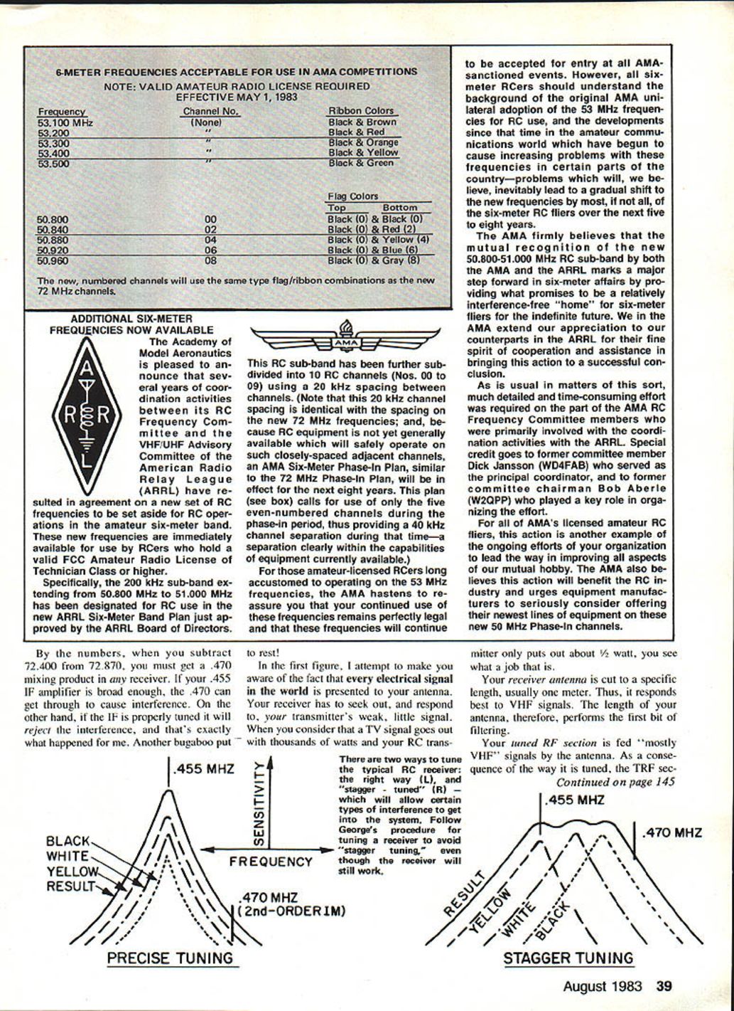
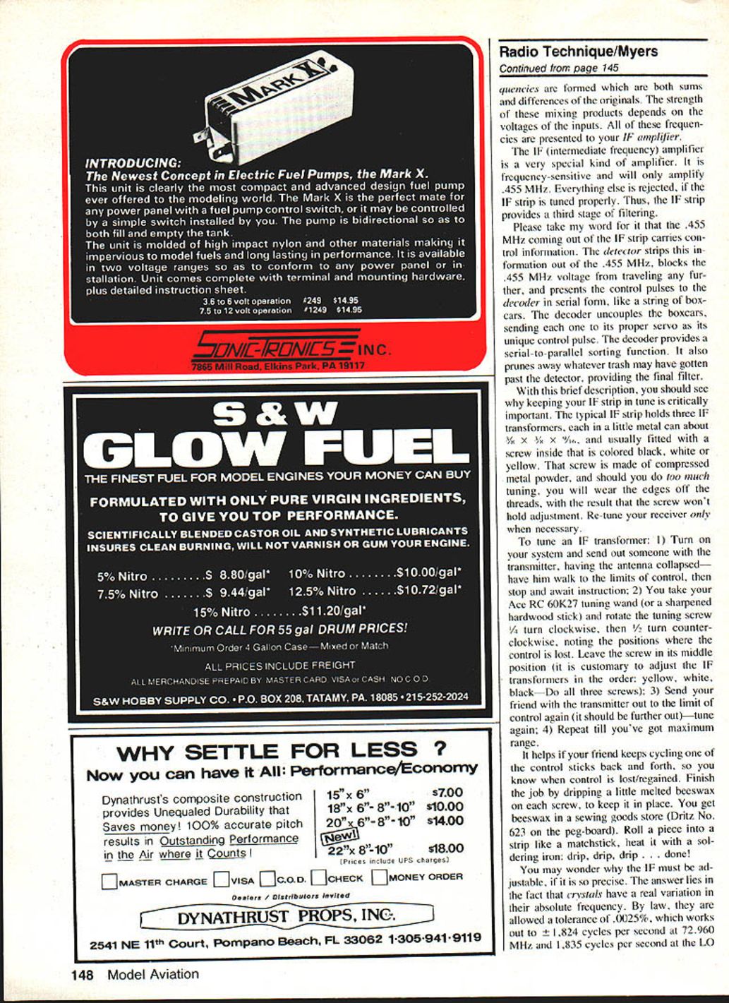
Precise Tuning vs. Stagger Tuning
There are two ways to tune the typical RC receiver: the right way (precise tuning) and "stagger-tuned," which will allow certain types of interference to get into the system. Follow the proper tuning procedure to avoid stagger tuning even though the receiver will still work when stagger-tuned.
Frequencies formed in the mixer depend on the voltages of the inputs. The strength of the mixing products depends on input voltages. All of these frequencies are presented to your IF amplifier; if the IF is sharp and tuned correctly, undesired mixing products will be rejected.
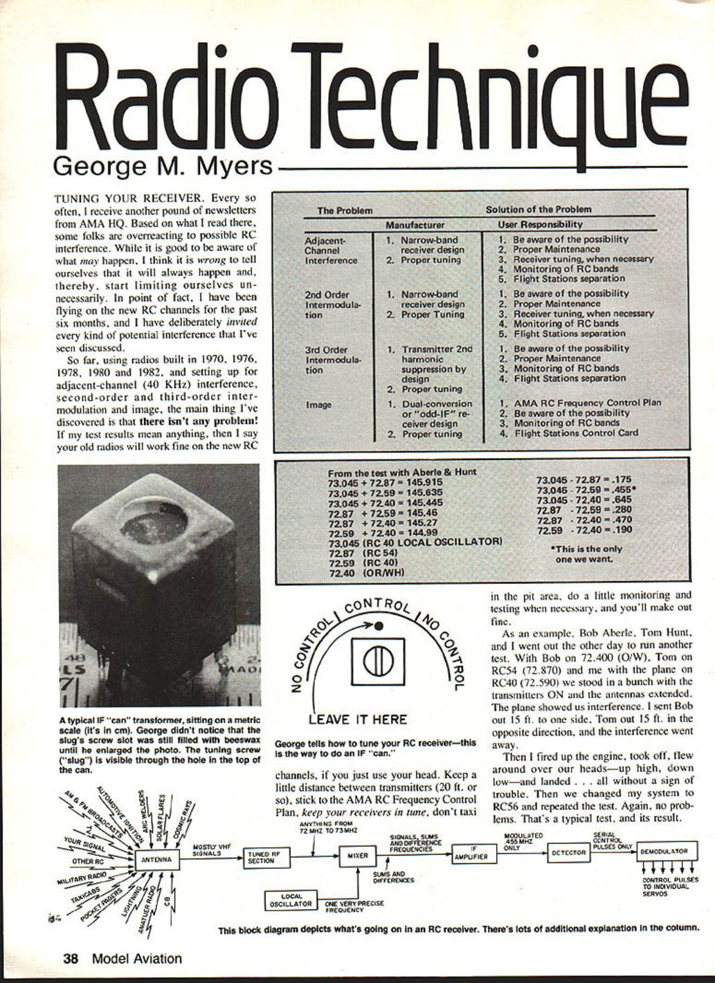
Tuning the IF Transformers (procedure)
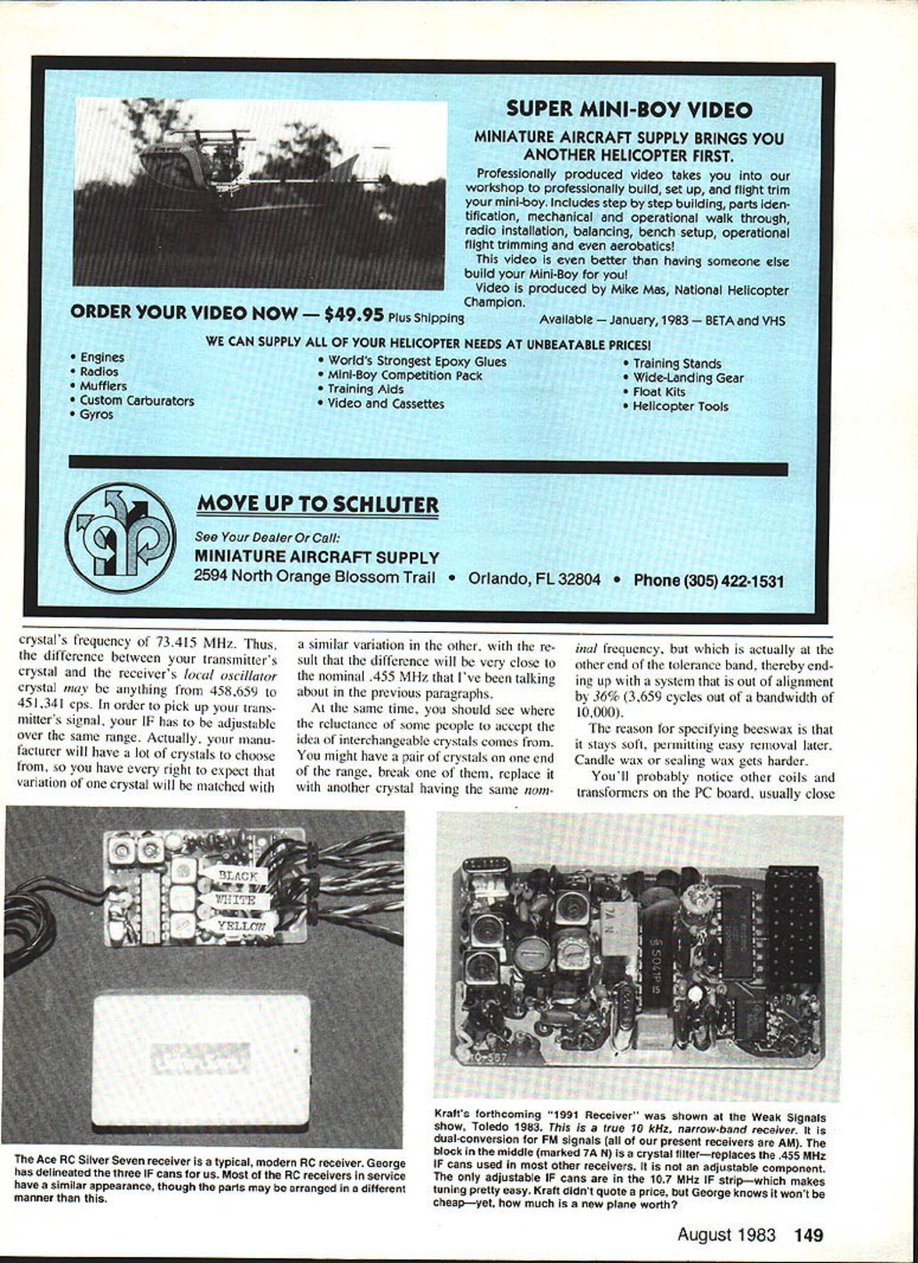
The typical IF strip holds three IF transformers, each a small metal can about 3/8" × 3/8" × 3/8", usually fitted with a screw colored black, white, or yellow. The screw is made of compressed metal powder; do not overtune or you will wear the screw threads and it won't hold adjustment. Re-tune your receiver only when necessary.
To tune an IF transformer:
- Turn on your system. Have someone take the transmitter (antenna collapsed) and walk to the limits of control, then stop and await instruction.
- Use a tuning wand (e.g., Ace RC 60K27) or a sharpened hardwood stick and rotate the tuning screw 1/4 turn clockwise, then 1/2 turn counterclockwise, noting the positions where control is lost. Leave the screw in its middle position. It is customary to adjust the IF transformers in this order: yellow, white, black. Do all three screws.
- Send your friend with the transmitter out to the limit of control again (it should be further out). Tune again.
- Repeat until you've got maximum range.
Tips:
- Have your friend keep cycling one control stick back and forth so you know when control is lost/regained.
- Finish by dripping a little melted beeswax on each screw to keep it in place. Beeswax stays soft and permits easy removal later (Dritz No. 622 is an available product). Roll a piece into a strip like a matchstick, heat it with a soldering iron and drip it on the screw.
Why the IF must be adjustable: Crystals have a real variation in absolute frequency. By law they are allowed a tolerance of 0.0025%, which works out to ±1,824 Hz at 72.960 MHz and ±1,835 Hz at a LO crystal frequency of 73.415 MHz. Thus the difference between your transmitter's crystal and your receiver's LO crystal may be anywhere from 458,659 to 451,341 cps. The IF has to be adjustable over this range to pick up your transmitter. Manufacturers will normally match crystal variations so the difference will be close to the nominal 0.455 MHz, but replacement crystals can create misalignment if they fall at opposite ends of the tolerance band. You might end up out of alignment by a noticeable amount (for example, 3,659 cycles out of a bandwidth of 10,000).
Other coils and dual-conversion receivers
You'll probably notice other coils and transformers on the PC board, usually close to the IF cans; these belong to the TRF section and rarely need retuning. Leave them alone, or you will waste a lot of time.
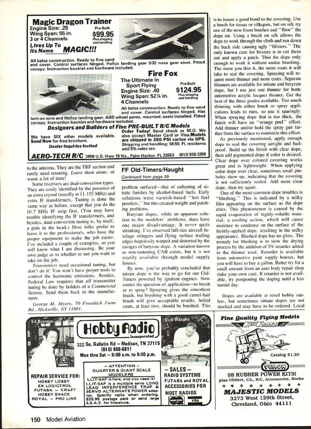
Some receivers are dual-conversion types and can be identified by the presence of an extra crystal (usually at 11.155 MHz) and extra IF transformers. Tuning is done the same way as before, except you do the 10.7 MHz IF strip first. Dual-conversion tuning can be tricky; most folks prefer to leave it to professionals who have the proper equipment.
Transmitters and legal note
Transmitters need occasional attention but do not tune them yourself. You won't have the proper tools to control harmonic emissions, and Federal law requires that transmitter tuning be done by holders of a commercial license. Send transmitters back to the manufacturer for servicing.
George M. Myers 70 Froehlich Farm Rd. Hicksville, NY 11801
Transcribed from original scans by AI. Minor OCR errors may remain.

