
Radio Technique
George M. Myers
GCA for Modelers?
I have a suggestion for Contest Directors: let's agree to use CB Channel 20 as a tool for locating contest sites. All that's required is to find a volunteer who will arrive at the contest site about two hours early with a CB base station and a map of the area. He can then monitor the channel and give information when necessary. If you can't use CB20 for some reason, list an alternative channel (or channels) in your contest announcement. But use CB20 wherever possible, for consistency. Most people who still use CB will keep it tuned to CB19 for traffic reports, so the assignment is logical and easy to find.
It is somewhat annoying to drive 100 miles to find out that the contest site has been relocated to some obscure empty field that you can't identify on a Rand-McNally map. But Rand-McNally will get you close enough for CB to take over. Think of it as your GCA (Ground-Controlled Approach) system.
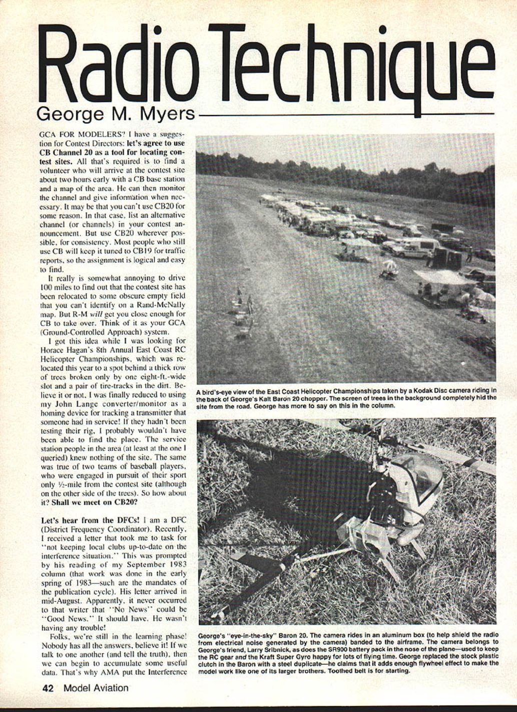
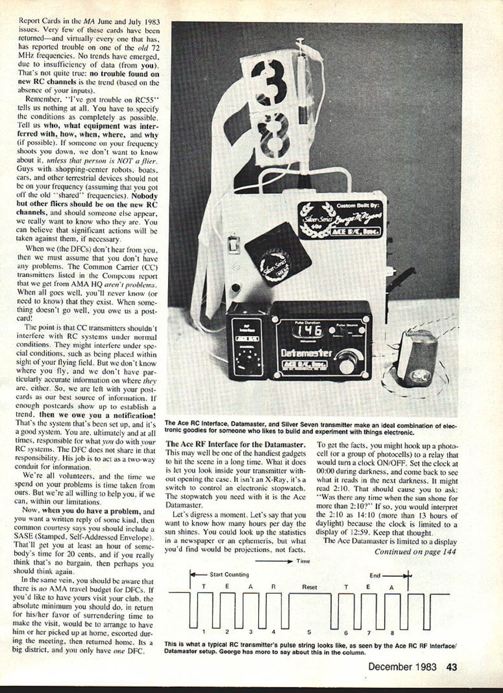
I got this idea while I was looking for Horace Hagan's 8th Annual East Coast RC Helicopter Championships, which was relocated this year to a spot behind a thick row of trees broken only by one eight-foot-wide slot and a pair of tire tracks in the dirt. Believe it or not, I was finally reduced to using my John Lange converter/monitor as a homing device for tracking a transmitter that someone had in service! If they hadn't been testing their rig, I probably wouldn't have been able to find the place. The service-station people in the area (at least at the one I queried) knew nothing of the site. The same was true of two teams of baseball players, who were engaged in pursuit of their sport only 1/2 mile from the contest site (although on the other side of the trees). So how about it? Shall we meet on CB20?
Let's hear from the DFCs!
I am a DFC (District Frequency Coordinator). Recently I received a letter that took me to task for "not keeping local clubs up-to-date on the interference situation." This was prompted by his reading of my September 1983 column (that work was done in the early spring of 1983—such are the mandates of the publication cycle). His letter arrived in mid-August. Apparently, it never occurred to that writer that "No News" could be "Good News." It should have. He wasn't having any trouble!
Folks, we're still in the learning phase. Nobody has all the answers. If we talk to one another (and tell the truth), then we can begin to accumulate some useful data. That's why AMA put the Interference Report Cards in the June/July 1983 issues of Model Aviation.
Report Cards
Very few cards have been returned, and virtually none has reported trouble on the old 72 MHz frequencies. No trends have emerged due to the insufficiency of data. That's quite true—absence of reports does not necessarily mean absence of trouble. A single note such as "I've got trouble on RC55" tells us nothing unless the conditions are specified completely. Tell us what equipment interfered, the circumstances, and whether the person reporting was a flier. We don't want rumors; we want facts.
Other terrestrial devices—shopping-center robots, boats, cars, and similar equipment—should be checked to see whether they are operating off old shared frequencies. If another flier appears on one of the new RC channels, we really want to know so that significant action can be taken if necessary. If DFCs don't hear, they must assume there are no problems.
Common Carrier (CC) transmitters listed in the CompComm report sent to AMA HQ are not expected to be problems under normal conditions; but you will never know unless you report if something doesn't go well. CC transmitters shouldn't interfere with RC systems under normal conditions, but they might under special conditions such as being placed within sight of the flying field. I don't have particularly accurate information on this either, so postcards remain the best source of information. If enough postcards show up to establish a trend, notification is owed.
That's the system that's set up; it's a good system. Ultimately, DFCs share responsibility and act as a two-way conduit of information. Volunteers who spend time investigating problems and reporting are appreciated, within limitations. If you have a problem and want a written reply, common courtesy says you should include a SASE (Stamped Self-Addressed Envelope). That'll get you at least an hour of somebody's time for 20 cents, and if you really think that's no bargain, then perhaps you should think again.
In the same vein, you should be aware that there is no AMA travel budget for DFCs. If you'd like to have yours visit your club, the absolute minimum you should do in return for his/her favor of surrendering time to make the visit is to arrange to have him or her picked up at home, escorted during the meeting, then returned home. It's a big district, and you only have one DFC.
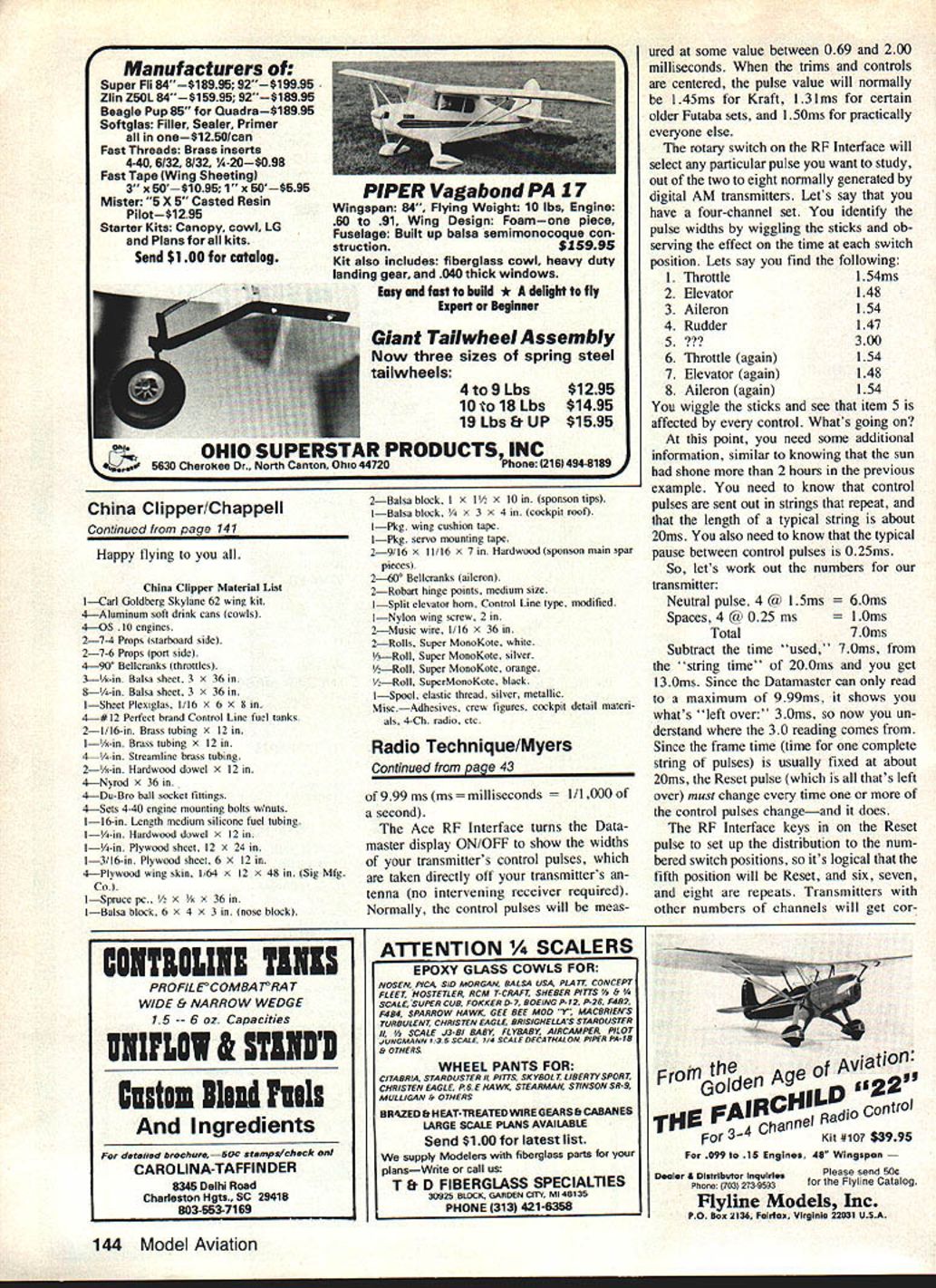
The Ace RF Interface for the Datamaster
This may well be one of the handiest gadgets to hit the scene in a long time. What it does is let you look inside your transmitter without opening the case. It isn't an X-ray; it's a switch to control an electronic stopwatch. The stopwatch you need with it is the Ace Datamaster.
Let's digress a moment. Suppose you want to know how many hours per day the sun shines. You could look up the statistics in a newspaper or an ephemeris, but what you'd find would be projections, not facts.
To get the facts, you might hook up a photocell (or a group of photocells) to a relay that would turn a clock ON/OFF. Set the clock at 00:00 during darkness, and come back to see what it reads in the next darkness. It might read 2:10. That should cause you to ask: "Was there any time when the sun shone for more than 2:10?" If so, you would interpret the 2:10 as 14:10 (more than 13 hours of daylight) because the clock is limited to a display of 12:59. Keep that thought.
The Ace Datamaster is limited to a display of 9.99 ms (ms = milliseconds = 1/1,000 of a second).
The Ace RF Interface turns the Datamaster display ON/OFF to show the widths of your transmitter's control pulses, which are taken directly off your transmitter's antenna (no intervening receiver required). Normally, the control pulses will be measured at some value between 0.69 and 2.00 milliseconds. When the trims and controls are centered, the pulse value will normally be:
- 1.45 ms for Kraft sets,
- 1.31 ms for certain older Futaba sets,
- 1.50 ms for practically everyone else.
The rotary switch on the RF Interface will select any particular pulse you want to study, out of the two to eight normally generated by digital AM transmitters. Let's say that you have a four-channel set. You identify the pulse widths by wiggling the sticks and observing the effect on the time at each switch position. Let's say you find the following:
- Throttle — 1.54 ms
- Elevator — 1.48 ms
- Aileron — 1.54 ms
- Rudder — 1.47 ms
- ??? — 3.00 ms
- Throttle (again) — 1.54 ms
- Elevator (again) — 1.48 ms
- Aileron (again) — 1.54 ms
You wiggle the sticks and see that item 5 is affected by every control. What's going on?
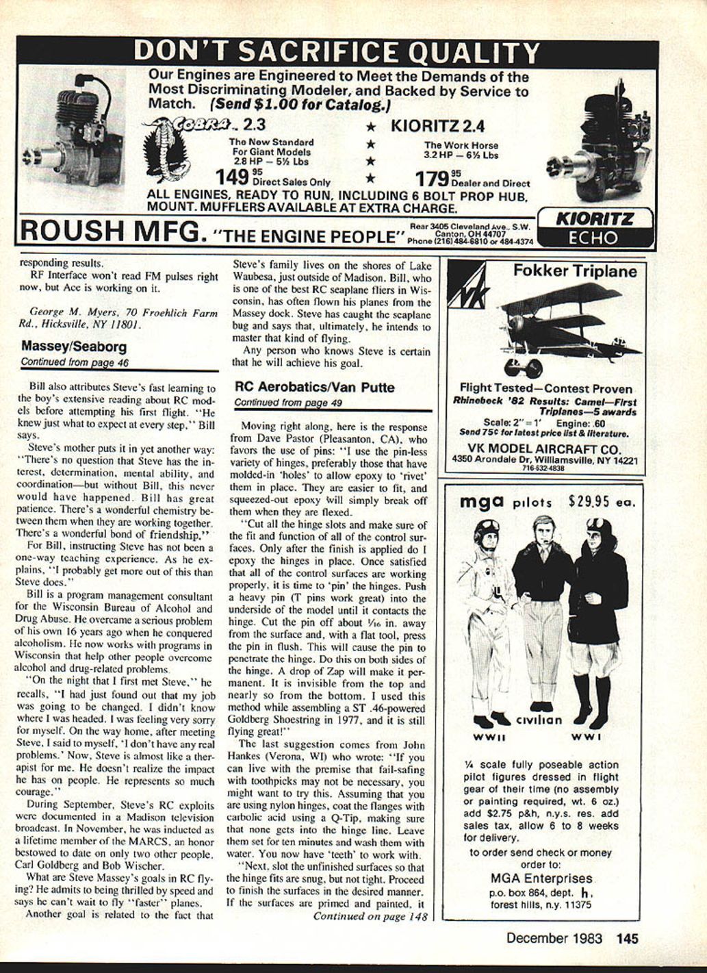
At this point you need some additional information, similar to knowing that the sun had shone more than two hours in the previous example. You need to know that control pulses are sent out in strings that repeat, and that the length of a typical string is about 20 ms. You also need to know that the typical pause between control pulses is about 0.25 ms.
So, let's work out the numbers for our transmitter:
- Neutral pulses, 4 @ 1.5 ms = 6.0 ms
- Spaces, 4 @ 0.25 ms = 1.0 ms
- Total used = 7.0 ms
Subtract the time used (7.0 ms) from the string time (20.0 ms) and you get 13.0 ms. Since the Datamaster can only read to a maximum of 9.99 ms, it effectively wraps and shows what's "left over" beyond the display limit: about 3.0 ms. That explains the 3.0 ms reading. Since the frame time (time for one complete string of pulses) is usually fixed at about 20 ms, the Reset pulse (which is all that's left over) must change every time one or more of the control pulses change—and it does.
The RF Interface keys in on the Reset pulse to set up the distribution to the numbered switch positions, so it's logical that the fifth position will be Reset, and six, seven, and eight are repeats. Transmitters with other numbers of channels will get correct orientation by the same reasoning.
The pulse width shown for Reset may also be affected by pulse repetition rate and by the width of the pulses; situations vary. Result: RF Interface won't read FM pulses right now, but Ace is working on it.
George M. Myers 70 Froehlich Farm Rd. Hicksville, NY 11801
Transcribed from original scans by AI. Minor OCR errors may remain.

